SERVING TRAYSAfter finishing up my
napkin holder
box project last month, I checked my wood inventory and had a few pieces of
fairly decent curly maple wood left from last year's
custom keepsake box
and wanted to do a few serving trays as special gifts and for personal usage
and/or decor. Excellent kiln dried Appalachian curly and figured maple is
available from
Border Maple Specialties owned by Dustin
Hensley in Gray, Kentucky and highly pleased with his products and excellent
fast service.
PERSONAL SAFETY AND LIABILITY ISSUES
My goal will be to keep Safety
paramount because hand and power tools can do serious bodily harm and death
if not used properly, therefore these pages are solely for
entertainment purposes only from
a personal liability standpoint. Please read the
Legal Stuff
page for additional information concerning liability issues
before going any further. Safety glasses and hearing protection is a must,
although I do forgo the hearing protection many times; my bad!
RECON AKA RESEARCH
I did some internet researching to ascertain some basic design ideas and
watched a few YouTube videos featuring Norm Abram of the New Yankee
Workshop and found out quickly that just cutting a
regular forty-five (45) degree angle on a slope doesn't fit unless you are
referencing your cuts from the actual slope you plan to use similar
to the way crown molding is cut using a miter saw or a miter box. Ole timers
call this type of cut a
hopper cut since you have tapering sides.
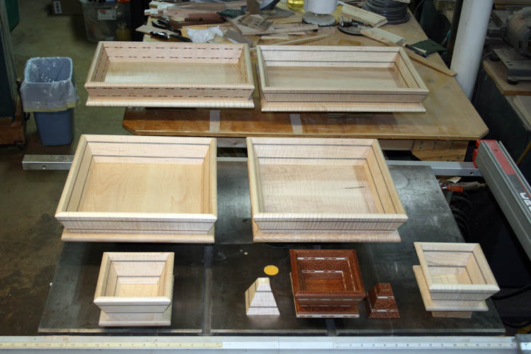
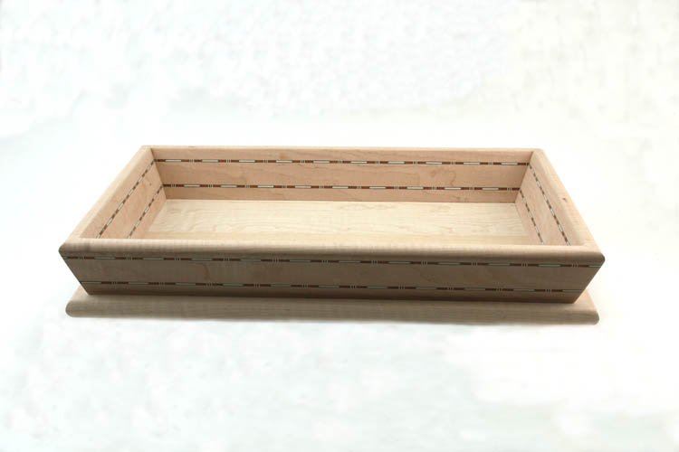
FINISHED SERVING TRAYS AND CANDY DISHES
GETTING STARTED
I rounded up some scrap material left over from a
toy box aka
blanket chest I made for our youngest grandson Xander McKnight Gonzales to
do some test cuts known as trial and error cuts.
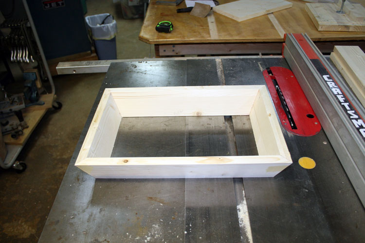
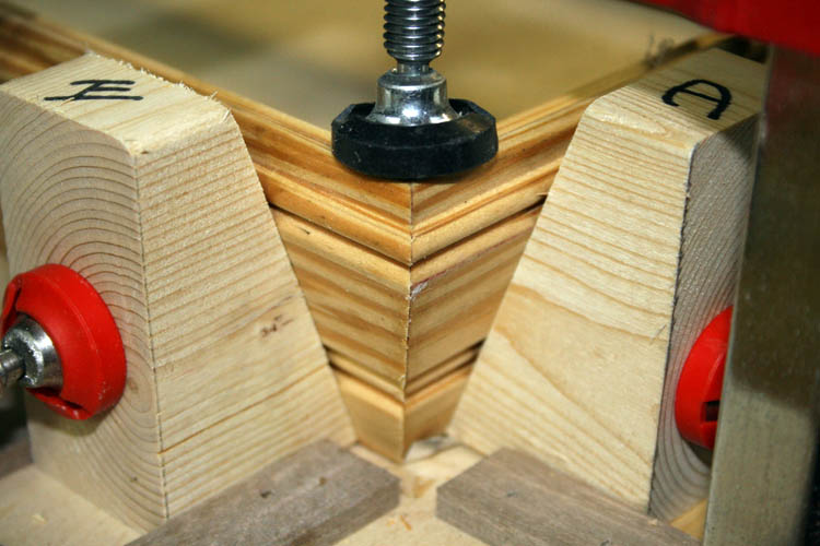
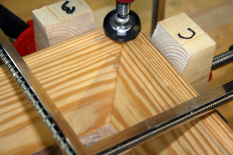
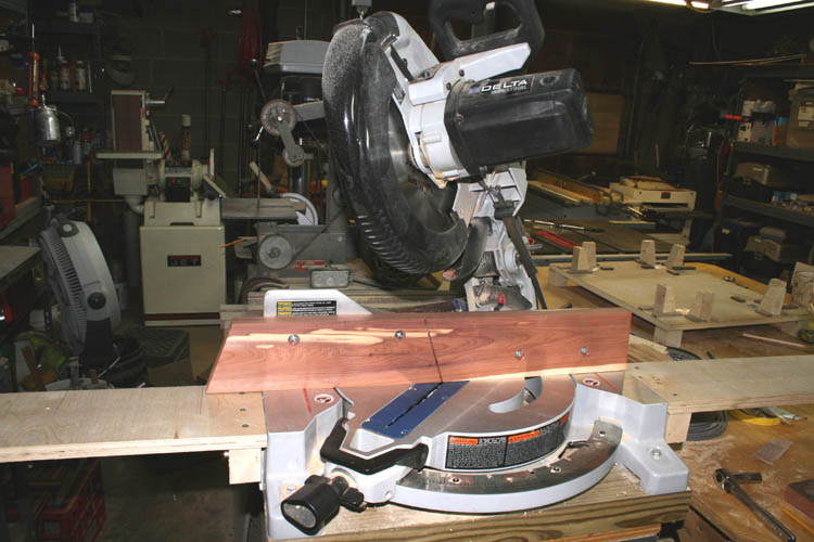
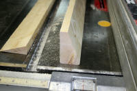
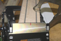
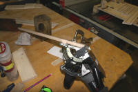
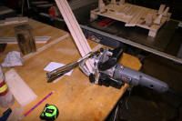
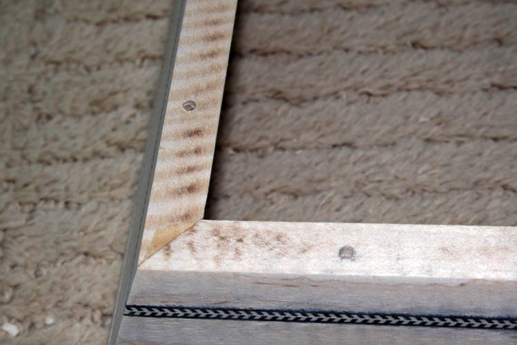
After making several test cuts using my compound miter saw, I had to
tweak the bevel and miter and got very close as depicted by the pix above.
I had the bevel and miter settings reversed but the cut still came out
pretty close. I think I have a mild case of dyslexia at times and
have to grin at myself when things don't come out as expected......grin if
you must! I found a chart via the internet showing what the bevel and the miter is for
the slope angle you desire and I was fairly close, except I had the miter
and bevel settings reversed which still worked. The problem with most
of the compound miter saws, their calibration gauges are not perfect and will get
you in the ball park pretty close. Changing the miter effects the
bevel and vise versa so it is a guessing game of trial and error using this
method of making the cuts for the slope, miter and bevel.
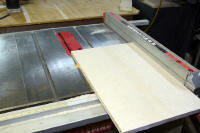
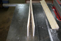
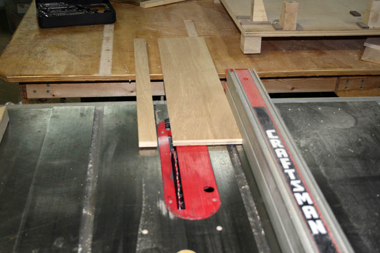
You have a matching angle to the top and bottom of each side and end
piece where the sides will be flush or flat with the base and that was cut
on the table saw with no problem.
Click on thumbnail pixs for a larger screen view:

I normally would have used my Starrett bevel protractor model C359 to
verify the angles but I stripped the cog that tightens down the slide in the
tool and will have to get it repaired at the Starrett factory or purchase
another used one off EBay.
SECURING THE CORNERS WITH GLUE AND DOWELS
Miter joints are not a strong joint and some type of reinforcement such
as a spline, dowel or biscuit is necessary since end grain doesn't glue very
well. Remember the old time way furniture and picture frame makers
used the corrugated nails which would split the wood and in time the joint
would pull apart if there was stress on it.
I decided to use the
Dowelmax
wood dowel system
for the corners and it worked great.
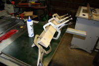
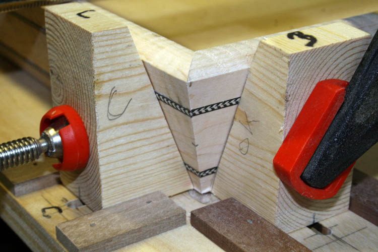
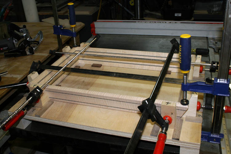
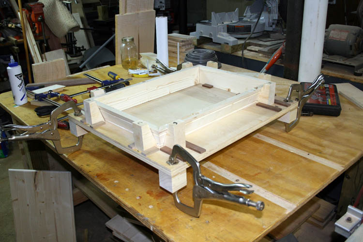
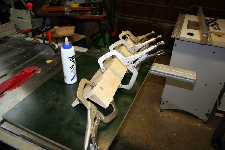
Another problem encountered was gluing the frame together with the dowels and keeping
everything square. I used a
Merle band clamp and also several
bar clamps but the Merle clamp will leave a mark in your wood due to the
pressure and the square corner of the clamp block meeting the 20 degree slope of the
sides. It was apparent, I needed to make a glue fixture since I plan
to make more than one. Making angle blocks just to fit the Merle clamp
wasn't feasible since there is only an inch or so of material to work with
on the Merle aluminum corner blocks.
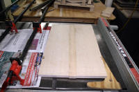
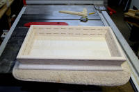
The base of the serving tray was made from a scrap piece of white pine
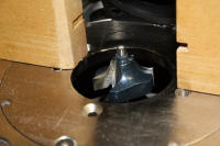
wood panel and cut to size on the table saw. The edges were rounded
over at the router table using a 3/8 inch round over bit.
Since this serving tray was solely for checking my set-up angle cuts,
etc., I did not affix the bottom but I might use it in the future for
something.
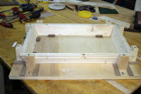
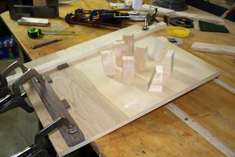
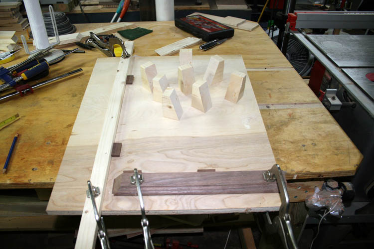
GLUE FIXTURE CONSTRUCTION
Using some 3/4 inch birch plywood panel, I cut a rectangle the size
needed for the gluing fixture allowing enough room for eight (8) angle blocks to
apply pressure at each corner.
Click on below thumbnail pixs for a larger screen view:


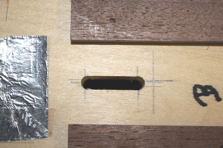
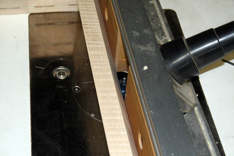
I used the router with an edge guide and 1/4 inch diameter solid carbide
two fluted router bit. The edge guide was nothing but a stick of wood
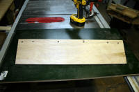
C clamped in place to reference off of and free hand routed the groove.
A screw was installed through the routed slot from the bottom of the fixture to each glue angle
block to keep the angle block in position along with a strip of wood glued
and braded on each side of the angle glue block where the block would only
travel forward and backwards.
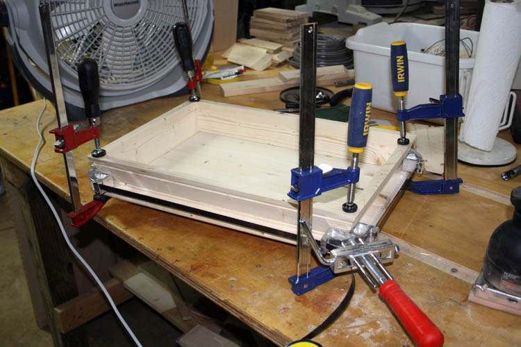
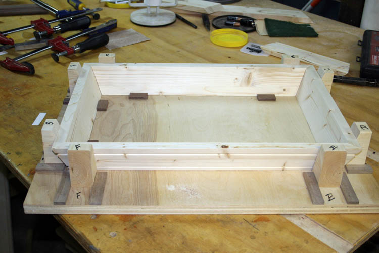
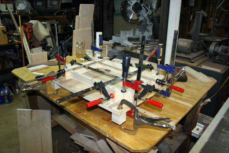
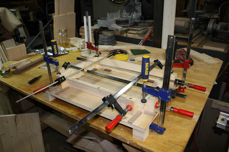
To keep the tray square while positioning in the fixture, I glued and
nailed small wood blocks at a right angle to keep the serving tray square.
Feet were also installed on each corner to keep the bar clamps off the table
while using the fixture. Four long bar clamps and four shorter bar
clamps are used to keep the serving tray square and level.
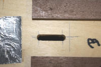
I double stick taped a piece of aluminum foil under each corner to keep
from gluing the serving tray bottom to the fixture and it worked great.
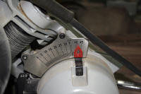
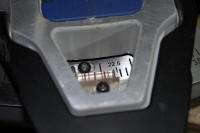
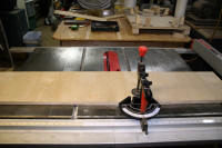
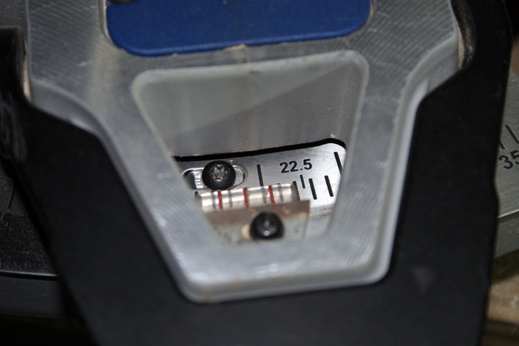
READJUSTING THE BEVEL AND MITER CUTS
After finishing the glue fixture, it was time to recalibrate or reset the
compound miter saw bevel and angle pretty close to what the chart calls for
when a twenty (20) degree slope is required and didn't have a separate
calibration tool to do so, having to make a few trial cuts on scrap
material.
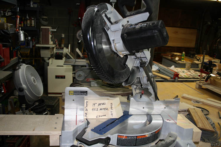
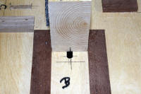
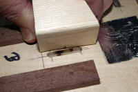
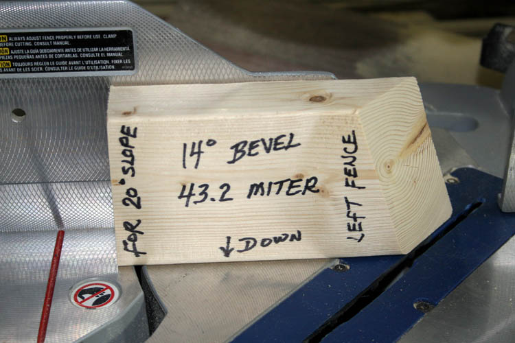
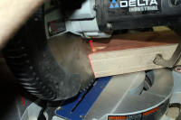
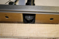
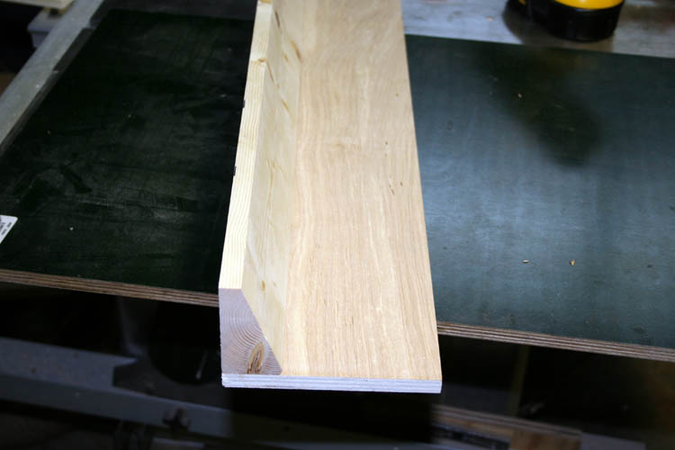
Below set-up block I made after doing some test cuts.
I made a total of three test serving tray frames and the last two used
some left over tongue and groove yellow pine bead board material which was
hard as a lightered knot. I used the above set-up block and the miter
and bevel was very very close although not perfect.
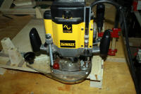
TWEAKING THE COMPOUND MITER SAW
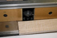
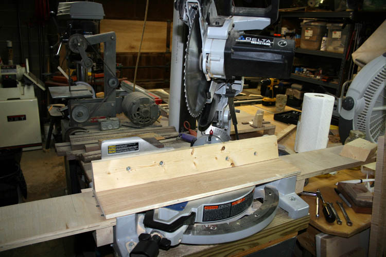
I decided to bolt a scrap piece of 1 inch thick cedar board to the miter
saw as a "sacrificial" backer
board to help keep the curly maple boards from splintering on the back side
of the cut; this would be the same thing as a zero clearance insert used on
your table saw to help prevent chip out and splintering.
I also added a short extension on either side of the miter saw frame
level with flat surface to allow the usage of stop blocks, however I only
used a stop block for the length and width of the cuts on the left side of
the saw being a simple block of wood and a C clamp.
TIME TO CUT SOME CURLY MAPLE
The curly maple boards were resized to 3/4 inch thickness using the
planer and cut to an initial width of 3 inches using the table saw. A
20 degree angle or bevel was cut on the bottom and top side of each piece of
material rendering the total height of the serving tray sides to be around
2.5 inches with the correct bevel to allow the sides to lay flat or flush on
the serving tray base; again using the table saw and changing the bevel of
the blade to 20 degrees instead of 90 degrees.
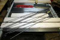
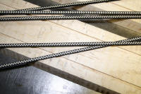
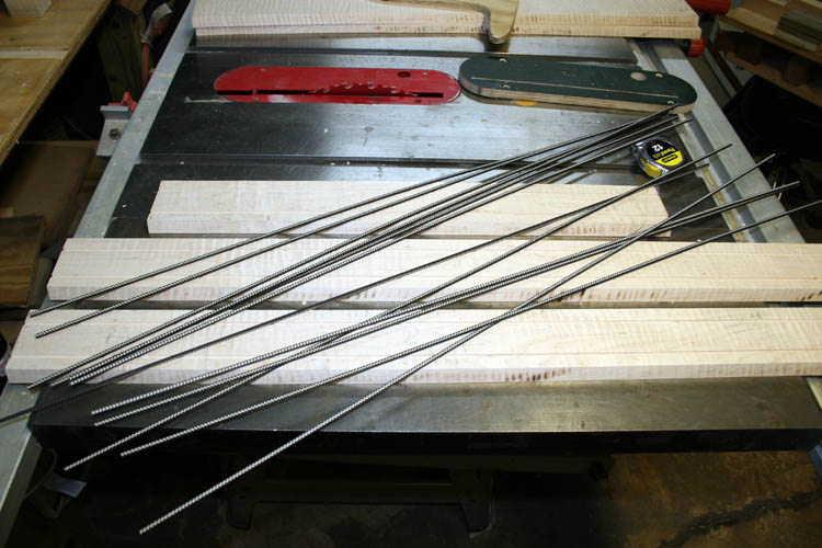
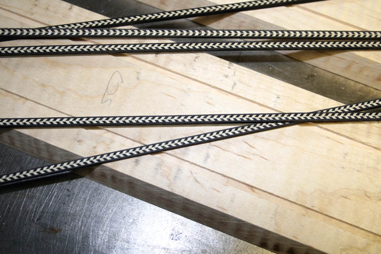
I routed two grooves on each side and end piece both outside and inside
to install wood marquetry aka wood purfling that I use on my turkey box
calls of which I also used and sold the same material when I had my musical mail
order business in the late 1960s through 1978.
Click on thumbnail pixs for a larger screen view:.

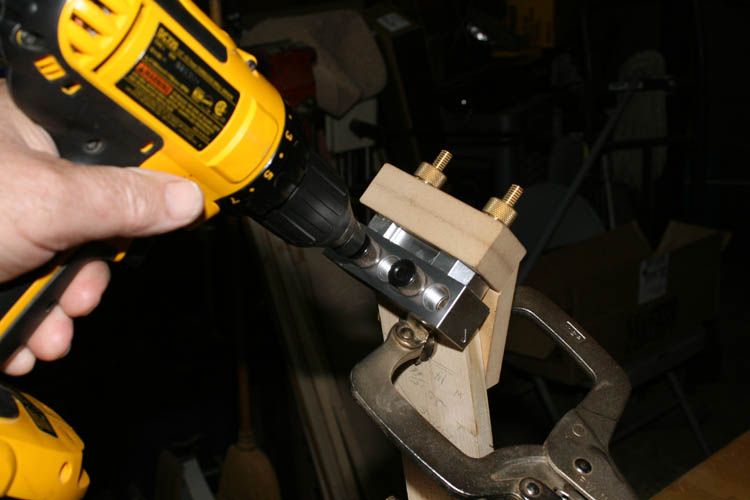
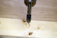
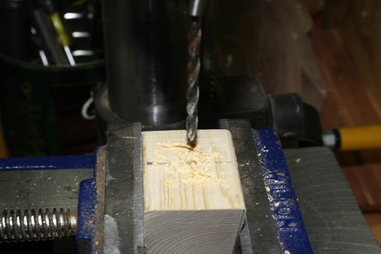
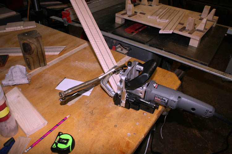
After cutting the sides and end pieces to length, I drilled holes for 1/4
inch diameter wood dowels using the Dowelmax jig.
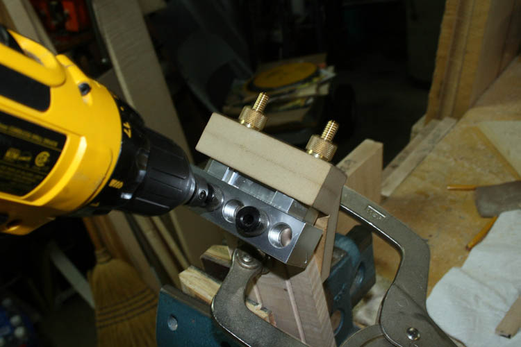
It was difficult to reference off the angled 2.5 inch width but got
extremely close with the jig. I had to open the holes up a little to
allow for not perfectly positioning the drill fixture to the angled wood.
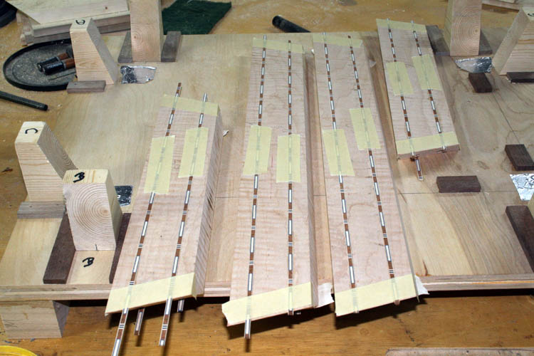
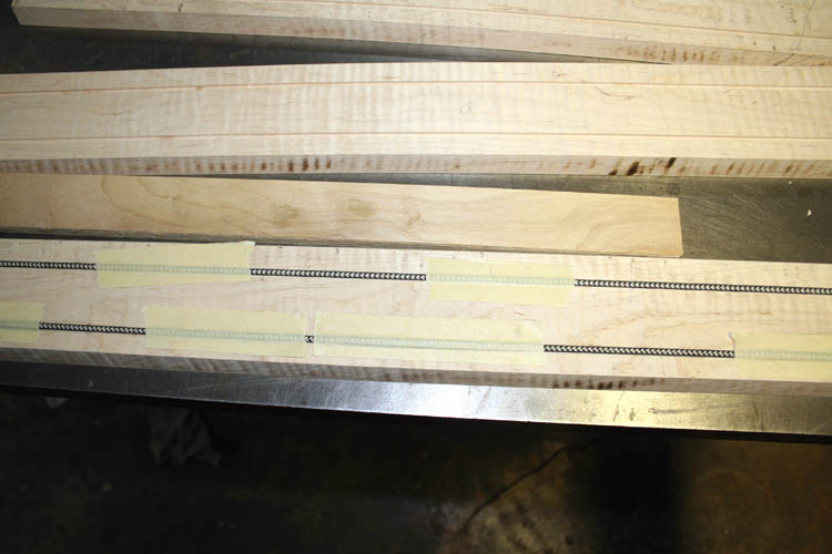
INSTALLING THE WOOD PURFLING
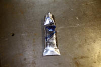
I used masking tape and
Fletch-Tite Platinum archery fletching glue to affix the wood
purfling to the serving tray sides and end pieces and allowed to cure
overnight. The wood purfling overhang was trimmed using a Stanly
utility knife to match the bevel and angle of the cut.
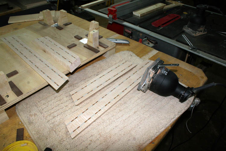
After trimming the ends to match the bevel and miter angle, each piece
was sanded with a pair of Porter-Cable model 330 speed block palm sander using 100 through 220
grit aluminum oxide sand paper.
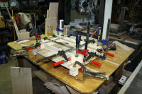
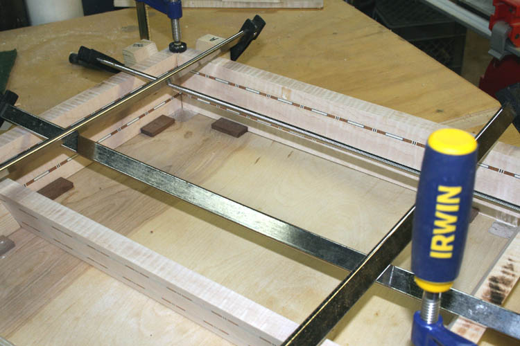
THE ACID TEST
The side and end pieces of the serving tray were headed to the glue
fixture and I had a difficult time getting the frame to square up.....I
believe my problem was installing two of the wood dowels before applying
glue to all the miters of which the Titebond II
extended time glue was still a little too fast open glue time but I finally
managed to knock the serving tray frame into alignment with the usage of a
wood block and hammer.
The frame didn't glue as tight as the last test piece I did in yellow pine
but it is still passable, however I seek as much perfection as possible with
my wood working projects. I think I will go back and tweak my compound
miter saw settings because I placed the yellow pine serving tray frame
against the sacrificial backer board and did see a discrepancy in the bevel
cut, small but
still noticeable. I now have a replacement Starrett C359 angle bevel
protractor and will calibrate my compound miter saw and/or built a fixture
to position the bevel of the cut to be made instead of using the bevel
adjustment on the compound miter saw. This will allow having to make
an adjustment to the miter only since the fixture will position the board in
the proper orientation as far as the slope of the sides goes. First, I
plan to re-calibrate the bevel and miter on the saw using the angle bevel
protractor before going to plan B making a fixture to hold the boards into
position with the slope desired. You could use a radial arm to make
the cut from above since you would not want to cut through your fixture.
A 10 inch table saw would not have enough blade extended above the table
depending on the thickness of your fixture to hold the board at the slope
desired.
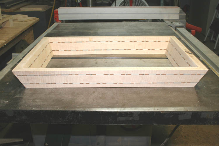
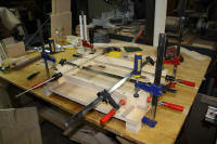
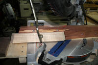
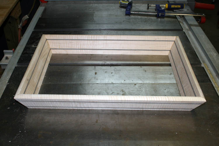
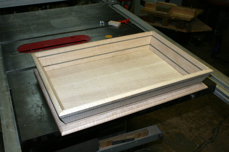
Above pix of the serving tray frame after glue-up. My next step
will be the routing of a radius on the outside top edge of the serving tray.
In all probability, I should have done this step before I cut the bevel and
angle of each end and side piece; but "six of
one and half a dozen of another." I ordered a 1/2
inch radius bull nose cutter to form the edge on the next serving tray base
and will not have to flip the base over but do the entire cut from one
reference side, however I still take several passes to do the routing rather
than do it all in one pass. Saves cutter life and is much safer!

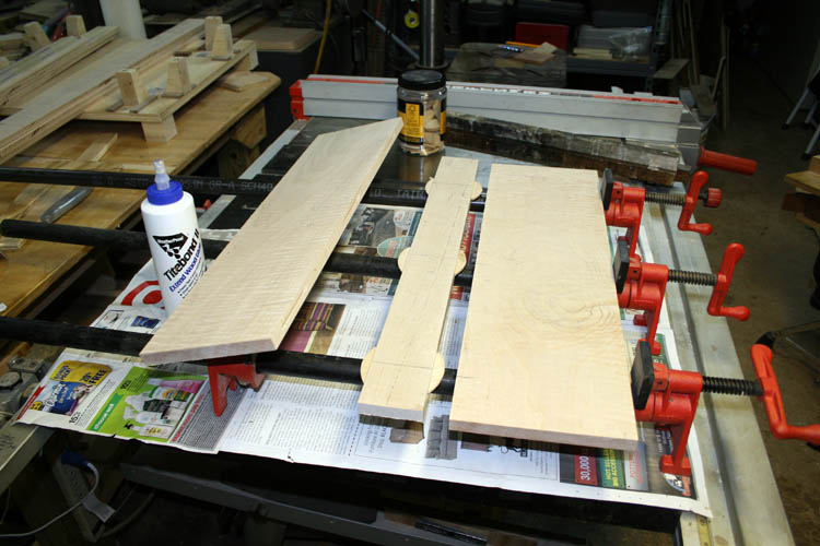
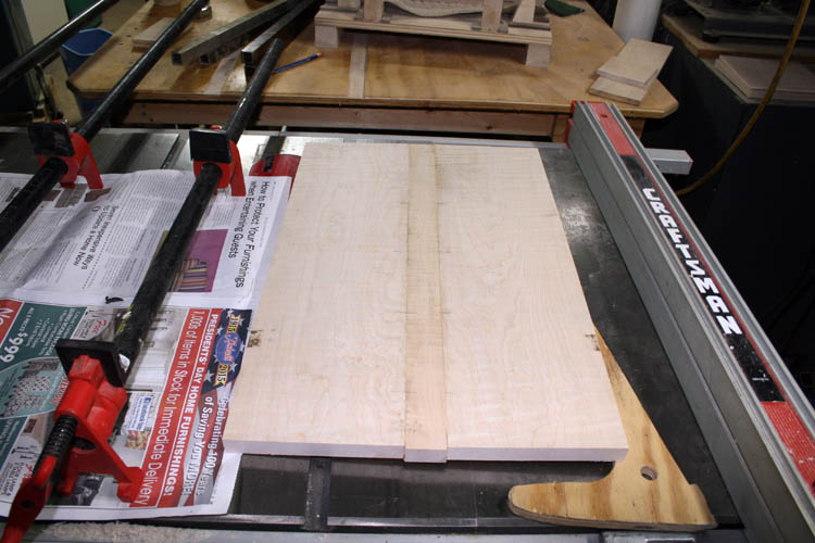
GLUING AND CUTTING THE BASE
The curly maple left from last year's project wasn't wide enough to do a
two piece glue-up and used a smaller 2 inch width strip in the center to give me the 14
inch width needed for the serving tray. I ran the boards through
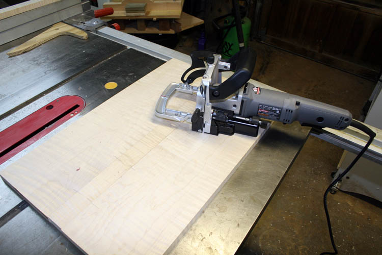
the planer and had them at 3/4 inch in thickness. The ole Porter-Cable
biscuit jointer was brought out of retirement and cut the slots for the larger size 20
biscuit. I rounded up a few bar clamps and secured the biscuits in
place using the Titebond II extended time glue which worked fine.
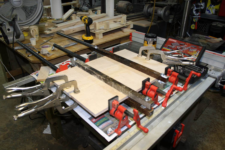
I used several bar clamps and a few pieces of heavy wall aluminum square
tubing to help keep the boards from bowing. The usage of the biscuits do a pretty good
job of aligning the boards for gluing and strength factor was not an issue
here. If strength was an issue, I would use 3/8 inch dowels.
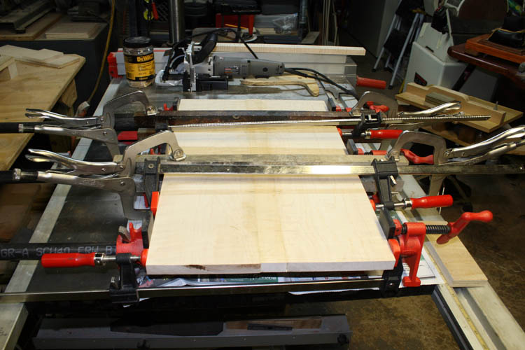
I applied enough pressure using the bar clamps to squeeze glue from the
three boards glue line and removed excess glue using a damp rag.
Click on below thumbnail pixs for a larger screen view:
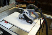
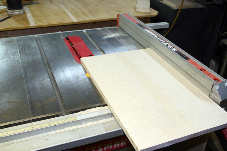
After the glue dried overnight, I scraped off what glue I could and then
used my Porter-Cable 4 x 24 inch belt sander with a 100 grit belt and
cleaned up the glue lines on both sides of the base. Next, it went to
the table saw and cut the width to 14 inches and the length to 20.5 inches
giving about a 3/4 inch overhang on the bottom sides and ends. I
routed a 3/8 inch radius on top and bottom of the base on the ends and
sides. The base was sanded using a couple Porter-Cable 330 1/4 sheet
palm sanders with grits from 100 to 220.
ATTACHING THE BASE TO THE SIDES
I did not want to glue the base to the sides because wood will move;
e.g., contract and expand in width due to the changing humidity levels even
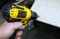
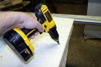
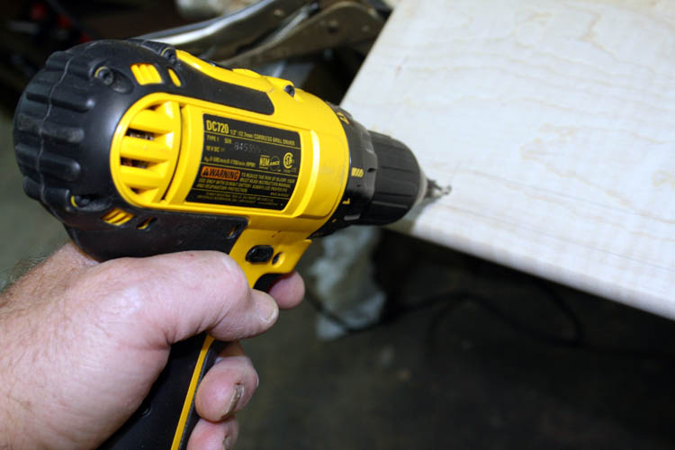
when properly sealed. I decided to use flat head wood screws and used
a few dry wall coarse thread 1 1/4 inch length screws and countersunk them below the bottom surface of the
base and elongated the holes in the base to allow for width expansion.
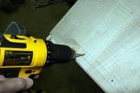
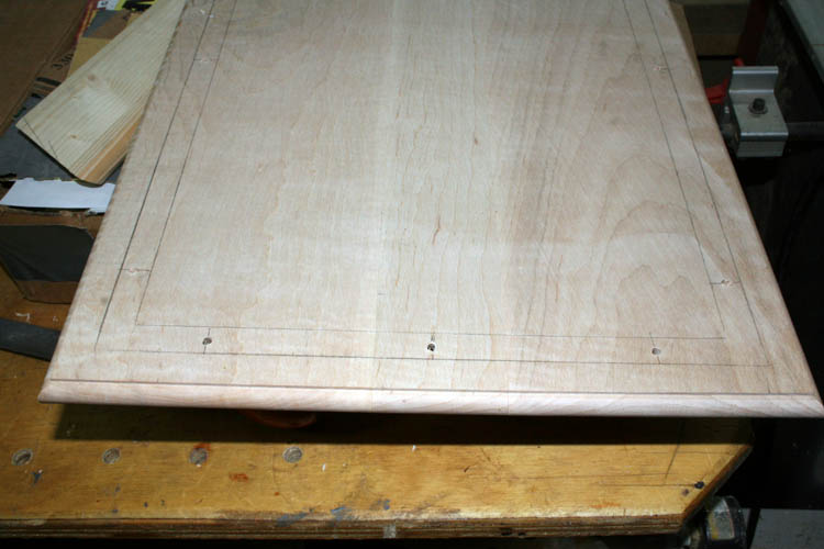
To keep from drilling the screws off center from the bottom of the base,
I first centered the serving tray frame on the base board and drew a pencil line
along the inside and outside of the sides of the serving tray to have
witness marks where I would have a reference on the base board. I used
one of the 20 degree slope blocks off the gluing fixture to help orientate the
drill bit at the 70 degree angle to match the 20 degree slope of the sides
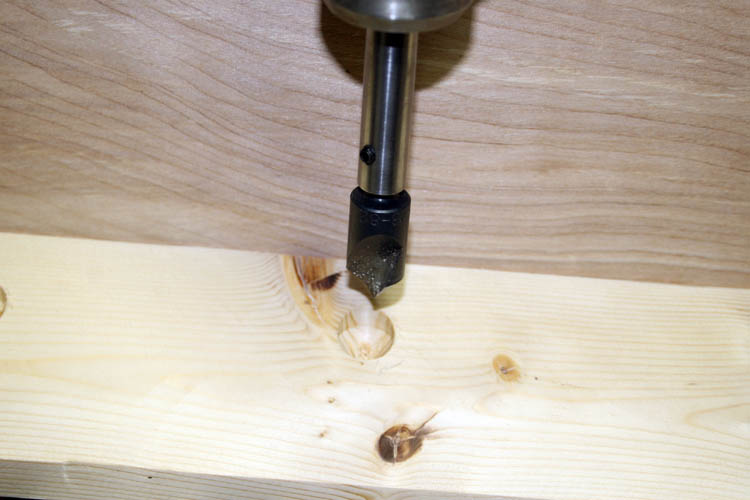
of the serving tray. I used a combination countersink and drill bit
for the # 10 size wood screws. I didn't taken many pixs of this
operation.....my bad!
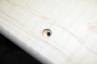
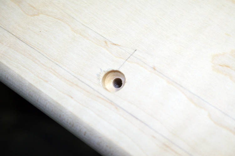
After drilling the holes in the base board, I then positioned the serving
tray side frame onto it and clamped them together. I drilled a small witness
hole through the base into the side frame and removed the clamps and checked to see if the
holes were centered and there was plenty of clearance from the side and end edges
and then drilled a tapered hole for the wood screws at the 70 degree angle
needed.
I will probably not install a plug over the screw holes or filler and
leave them just countersunk before I apply the sealer and finish
coats....depends on how it looks. The bottom of the base is not seen
anyway.
If I were doing a serious quantity of identical size serving trays, I
would build a drill fixture using hardened drill bushings to precisely
locate the position of each hole but that is not the case for this short run
project!
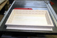
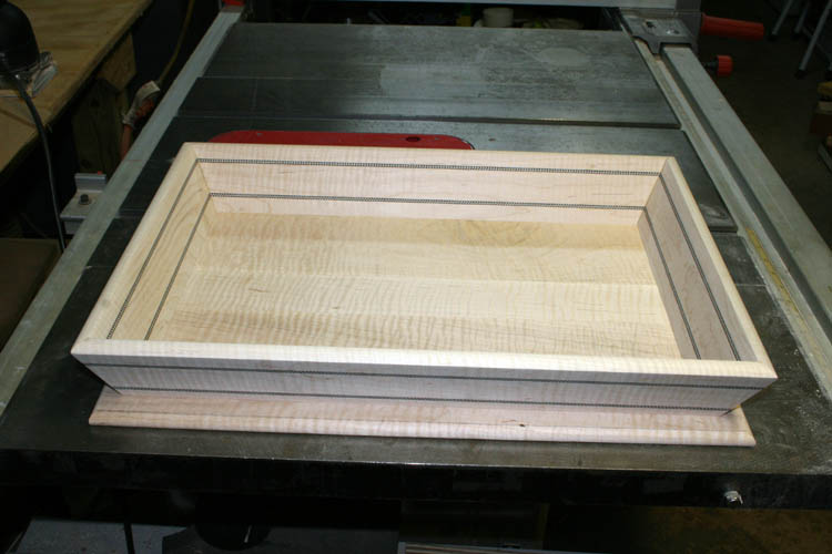
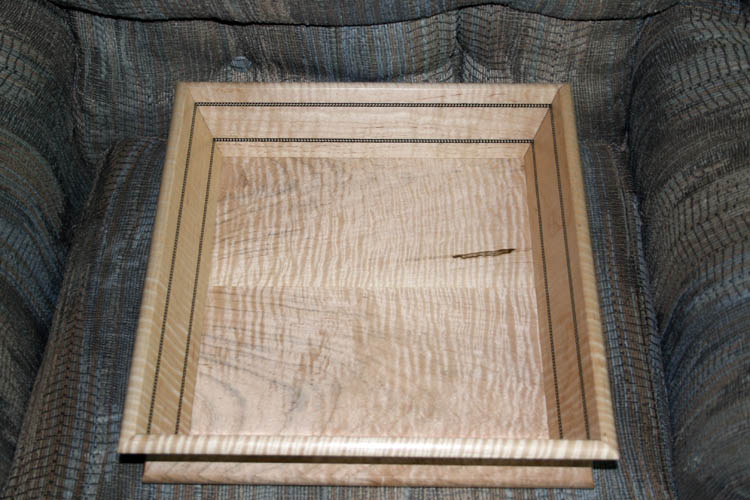
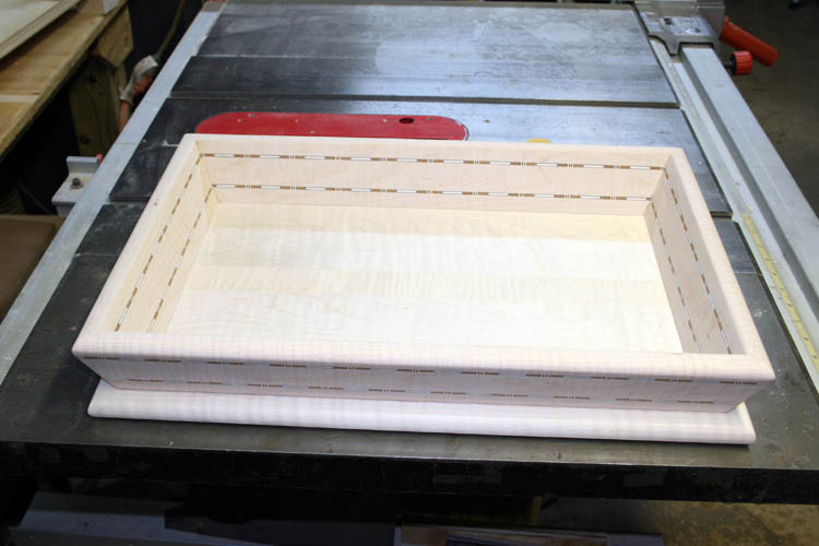
SERVING TRAY ASSEMBLED PRIOR TO FINISHING - SN 55
Below is a pix of the assembled serving tray without any finish.
The pix
doesn't do it justice because the curly maple grain did not show in the pix
but will do so when the finish is applied. I could have cheated a
little and wet the tray down with water but didn't want to raise the wood
grain at this time.
I will decide whether I plan to plug the screw holes or leave as is and
then start with a sealer coat and multiple coats of Mohawk Musical Grade
Instrument Nitrocellulose Lacquer.
In all probability, this serving tray will see more service as decor or a
craft display item! I might wait until I get several of them completed
before I apply the finish to get more economical usage out of the spray
equipment due to the cost of lacquer thinner required to cut aka thin the lacquer and do
the clean-up of the spray gun.
Web published by Bill aka Mickey Porter on 07-20-16.
FIXTURE FOR THE "HOPPER" CUT
As stated earlier, I plan to built several of the serving trays and
decided to construct a fixture or jig to make the
hopper cut or tapered bevel cut and
reference off the twenty (20) degree slope of the fixture. This would
allow the compound miter saw to make a vertical ninety (90) degree straight cut
(zero degree bevel) and a
regular forty-five (45) degree miter cut since the fixture will position
your material at the 20 degree slope. It might sound confusing but not
as confusing as the prior method I used.......grin if you must! If you change the slope
portion of the jig, it will not effect the 90 degree vertical cut or the 45
degree miter cut; basically the same way picture frame makers use their
fixed angle 45 degree right and left chop or shear knife blade machine to
make the cuts for that type of picture frame. In essence, making a
ninety (90) degree vertical cut at a forty-five (45) degree miter angle with
the material to cut positioned at the slope angle desired .
Click on below thumbnail pixs for a larger screen view:


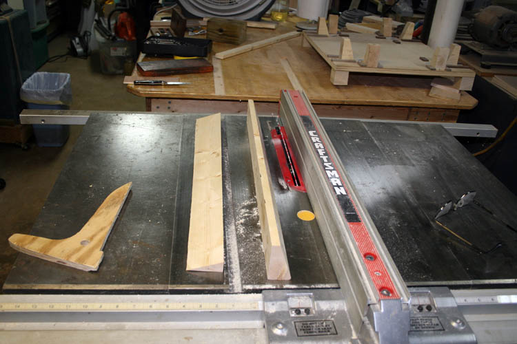
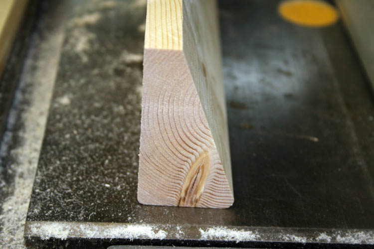
To build this fixture, I used a piece of scrap 2 x 4 framing stud about 2
feet in length and cut a 20 degree slope on it using the table saw.
Before I made the slope or bevel cut, I reduced the width of the 2 x 4
(which is about 3.625 inches) about 3/4 to 1 inch because the 10
inch table saw blade will not extend above the table enough to make the cut
in one pass. I
could attempt to invert the 2 x 4 and finish the cut with the
standard 2 x 4 width but I felt safer doing it the way I did since the
height wasn't too critical of an issue, although I had to drill two holes in
the left rear fence of the compound miter saw because the two original holes
were positioned too high.
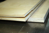
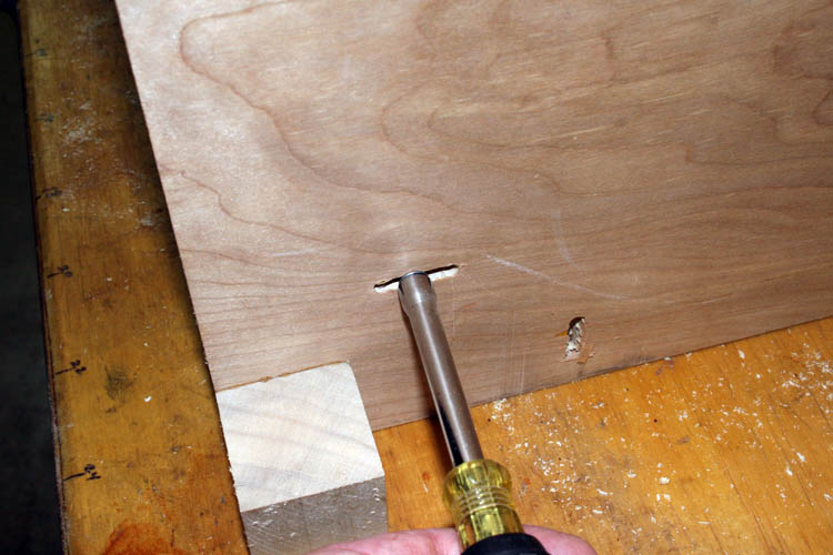
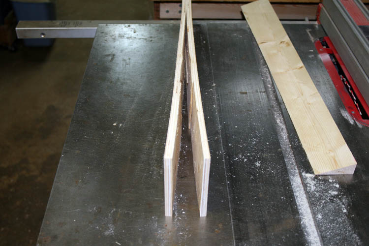
Some of the left over 3/4 inch birch plywood I had on hand did not pan
out. When I ripped it to the
width needed, it actually came apart as evidenced by a couple of the pixs
above indicating glue failure and/or improperly dried and cured piece of
plywood. It was too large an area to try and glue back together and I
had a spare 2 x 2 feet x 1/2 inch thickness birch plywood panel that came from Lowe's and ripped
what I needed from it. The other 3/4 inch 4 x 8 feet birch plywood panel came from our
local Wadesboro Lumber Barn and some of their stuff is nothing but
seconds in my humble opinion........most of the time, you get what you pay for.
Locally, The Wadesboro Lumber Barn is the only source for building supplies
since H. W. Little, Inc., no longer stocks all the various building
materials and supplies, only a few lumber items mostly molding, trim., etc.
H. W. Little, Inc., has joined the ranks of a Reader's Digest Hardware, in
all probably due to Lowe's and Home Depot within driving distance cutting
deeply into their profit margin!
After ripping the 1/2 inch plywood base for the piece of 2 x 4 stud that has the 20 degree slope
cut, I glued and screwed the 2 x 4 with the slope to the plywood base. I positioned
the fixture onto the compound miter saw table and transferred the two
existing holes in the back right side fence onto the fixture. The left
fence existing holes were too high and had to drill two 9/64 inch diameter holes
positioned lower through the fence to secure the slope aka hopper fixture.
I drilled a 120 degree countersink hole and then a 5/32 diameter 118 degree
hole followed by a 9/64 inch hole. The standard 118 degree drill bits will self-center itself into
the 120 degree countersink hole drilled. The fixture was secured to the miter
saw fence using four 1/4 x 20 machine screws and nuts; two were 1.5 inches in
length and 2 were 2 inches in length.
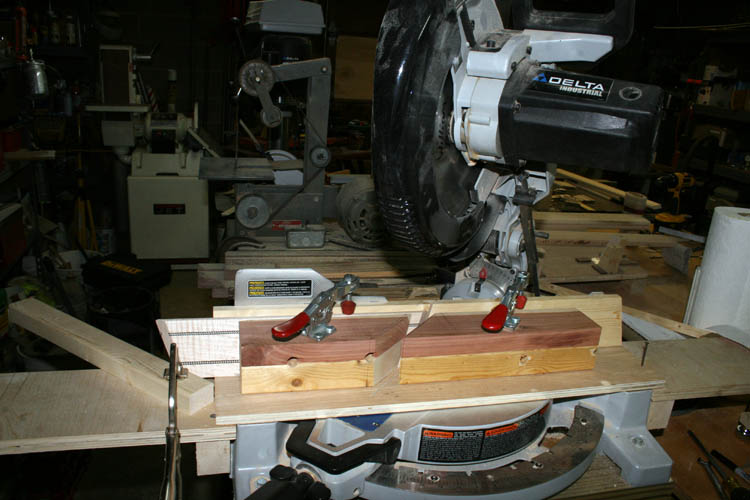
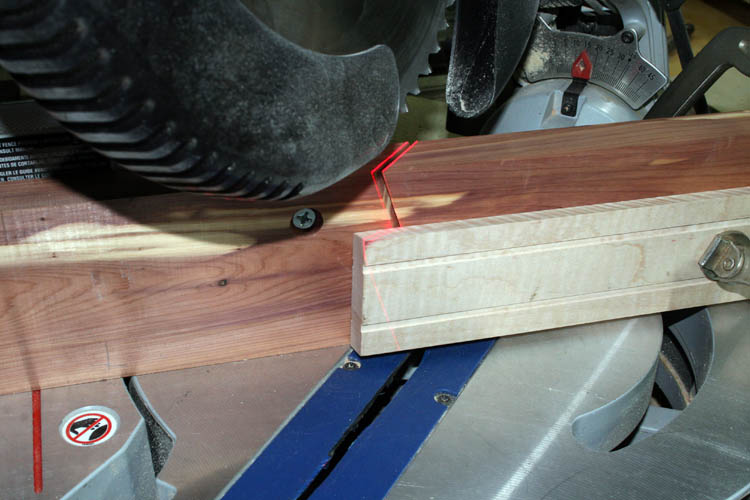
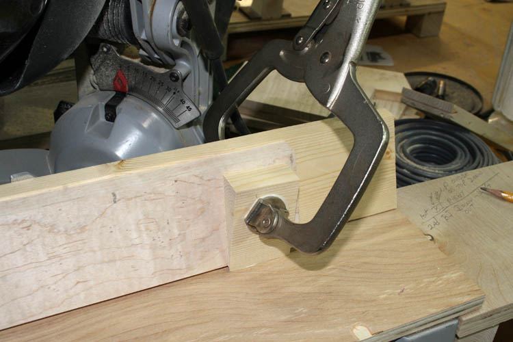
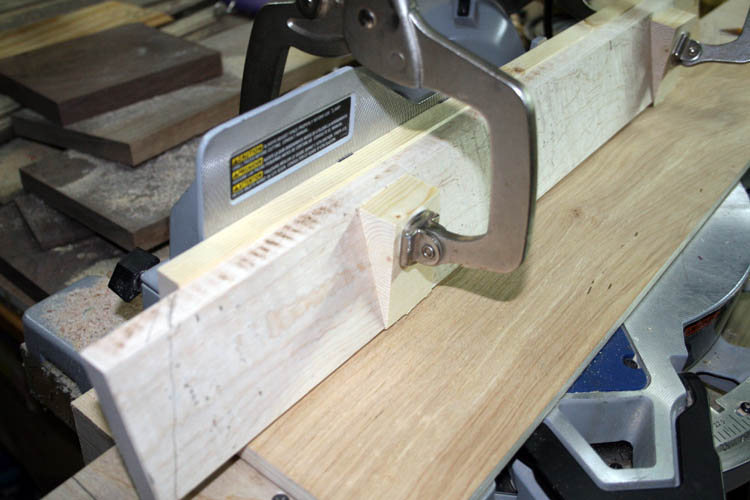
Above fixture ready to make some cuts. The boards to cut, will be
secured to the fixture slope using an adjustable Erwin 11SP locking C clamp
with swivel pad which will have a 20 degree wood block temporarily glue to
one of the moveable contact pads to keep the clamp from slipping. If I
were going to use the same thickness sides on every serving tray I make, I
would position a horizontal safety strip the length of the fixture onto the
base to help
position the bottom of the wood material but with a pair of the Erwin 11SP
clamps, it will not be necessary since I haven't experienced any trouble
with the board moving when just using the board against the miter saw fence.
If there is a problem, I can always go to plan B but do not foresee one at
this time. I already checked the
forty-five (45) degree miter angle setting and it matched the angle pretty close to the
Starrett C359 vernier bevel protractor set at forty-five degrees. I did a test cut on scrap material prior to
securing the fixture to the miter saw and the two forty-five degree cuts were dead on the ninety (90) degree
reference Starrett Machinists Square.
I milled several curly maple wood boards down to .540 inches in thickness and
ripped the side pieces to 3 inch in width and cut a 20 degree bevel on the
bottom side for resting flat onto the base of the serving tray.
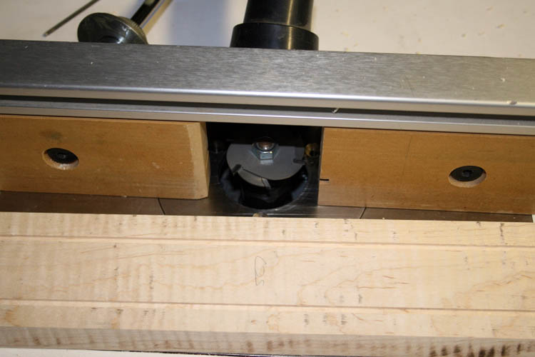
Tomorrow, the Lord willing of course, I plan to route the top of
each side and end piece using a bull nose router bit in my table router.
I will decide what type of wood purfling I plan to use and might use some
black white herringbone for contrast. Then, it will be time to cut the
forty-five (45) degree miters on the ends and sides of the serving tray. I already planed
aka milled three curly maple boards down to
.540 inches using the planer and will cut them to rough length and join the three boards
using glue and biscuits.
Web published update by Bill aka Mickey Porter on 07-24-16.
SERVING TRAY # 2 - SN 56


Click on above thumbnail pixs for a larger screen view and many of the
pixs will be redundant from the first serving tray. Today is July 25,
2016; I fabricated a couple clamp blocks using scrap material from the 2 x 4
hopper fixture and glued a piece of sandpaper to them and attached them to
the Erwin 11SP C clamps. I rounded over the top edge of each side and
end board of the serving tray using a 1/2 inch radius bull nose bit in the
router table only using about half the radius cut. I then changed the
router bit to a slotting cutter to match the width of the black/white
herringbone wood purfling and routed two grooves on each side of the side
and end boards.
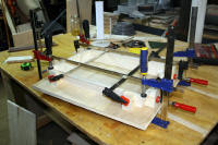
The edges of the boards for the serving tray base were run across the
jointer for a square and straight edge and cut biscuit slots for the size #
20 biscuits using my Porter-Cable biscuit jointer. The three boards
were then glued together with Titebond II glue with pressure applied using
three bar clamps and a pair of homemade 1 inch square aluminum heavy wall
tubing clamps to make certain the three boards remained flat since bar
clamps can cup the boards if not held perfectly flat against the clamp bar
and the square tubing clamps does keep the glue-up flat. It might bow
up like an early Cyprus Cajun
pirogue boat when the clamps are released but hope it doesn't.
The square aluminum tubing is getting double duty since I use them to
hang sausage items in my
smoker.
After the glue dries on the wood purfling sides, end boards and the
base of the serving tray; tomorrow, I will give the hopper fixture its first
run. Normally, I would do some testing on scrap material but I am
confident with the angle setting of the miter saw and the hopper jig will
take into account the 20 degree slope built into the fixture. This
certainly is "throwing caution to the wind" but it is about foolproof,
but as posted many times on this website,
"Murphy's Law Never Sleeps".
Hopefully, I will not have to
eat crow.......grin if
you must!
Web published update by Bill aka Mickey Porter on 07-25-16.
MODIFICATIONS TO THE HOPPER FIXTURE
I got ready to cut the miters on the serving tray components and when
clamping the wood to the slope on the hopper fixture, my Erwin 11SP clamp
and gluing caul aka wood angle block would not hold fast but wanted to slip
upward. It worked fine when testing it out on 07-25-16 making some
cuts but that is the
way it goes sometimes. I surveyed the scene to ascertain how I wanted to
secure the wood against the slope on the hopper fixture and decided to trap
the wood between the rear slope of the fixture and add a matching parallel angle piece
of wood in front of the rear slope and leave only enough room plus maybe
.010 inches clearance. I wanted to design the block where I could
adjust it in case I decide to use something thicker than the .540 material I
am currently using. I used a pair of DeStaCo 225U toggle clamps
off my napkin holder fixture to exert downward pressure on the top edge of the serving tray side
and end pieces.
This idea opened up several more things to do since the hopper fixture is
bolted to the rear fence of the miter saw and couldn't just simply attach
the angled block just mentioned onto it since the birch plywood is only 1/2
inch thickness and screws would need to be placed on the back side of the
birch plywood base plate. I could have glued the block in place but
that would not leave any room for later adjustability.
In order to install and access the 1/4 x 20 machines screws to secure the
hopper fixture to the miter saw, I drilled four 1/2 inch diameter plus holes
into the side of the front parallel angle blocks. I also needed to be able to see
where my reference saw cut line was located on the board to cut and cut
about an inch from the center section with a matching parallel angle cut.
The 1/2 inch diameter access holes will allow you to install and remove the
fixture as needed. Next, was positioning and
mounting 2 DeStaCo 225U toggle clamps to hold the serving tray side and end
pieces while making the appropriate cuts. I did not install any brass
inserts for 1/4 x 20 machine screws but used eight (8) large sheet metal flat head screws and drilled a pilot
hole for them.
After the additional clamp blocks and toggle clamps were installed with
the fixture bolted back to the miter saw rear fence, I made some test cuts
on the side pieces. You cut a miter on the ends of all the boards you
plan to use with the board positioned to the right side of the rear fence.
There is only one way the miter cuts can be made and a stop block is
positioned on the left outboard table extension to control the length of the
short sides and also the length of the long sides.
The sequence for using the hopper fixture as follows. 1) The first cut
will be made on the two short side and the two long side members with the
outside top down,
inside toward the fence and use the right portion of the hopper fixture.
Secure the board in place using the right side toggle clamp. 2) The
second serious of cuts will be made using the left side of the hopper
fixture with the boards positioned with the top up and outside toward the
fence. Place the previous cut miter against a stop on the left out
feed extension on the miter saw and secure the board in place using the left
toggle clamp on the fixture. Make the cut and duplicate the length of
the member you just cut whether it is the short side member or the longer
member.
I made one serious error since I had only three (3) pieces of side
material that I already had routed and glued the strips of black/white
herringbone wood purfling aka wood marquetry and two of the pieces were long
enough to get one long side and the other long piece would yield two shorter
end pieces. The other board would yield only one longer side. To
make a long story short, I didn't have the ole brain engaged and cut the
piece that would yield one longer side and cut a shorter side member from
it. Now, I cannot cut two longer sides and have only enough material to cut
the remaining shorter end piece. I had three curly maple boards that
were already sized to the proper width and had a angle cut for the bottom
and the top edge was routed with a bull nose router bit. My router
table was still set up with the slotting cutters for the herringbone wood
purfling and and had to route four slots for the wood purfling and now we
are back to square one.
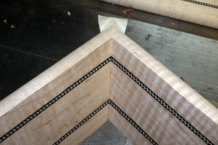
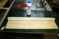
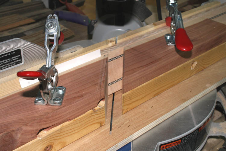
Above pix of the two side members just held together with masking tape
and it is going to be a decent fit.
CUTTING BISCUIT SLOTS
I got the Porter-Cable biscuit jointer out and started setting it up for
a number 0 size biscuit and shortened the length of cutter travel by about
.062 inches. This was a little tricky getting the slope angle plus the
forty-five (45) degree miter angle positioned onto the base and guide of the
biscuit jointer. After a few cuts on scrap material, I was ready to go
with it.
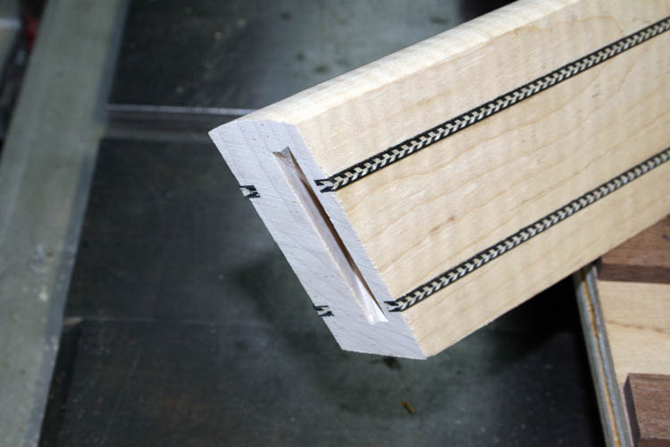
You don't have much room for error with the .540 thick board and getting
the slot as close to the inside miter was a little difficult. I got
the board in position and C clamped it while I cut the slot.
The glue dried enough and cut the remaining long side member to length and cut
biscuit slots into all the miter joints. I did a test mock-up without any
glue and everything fitted together real well. However, when I glued
the components in place, I had trouble getting everything square and
aligned, apparently the biscuits swelled too quickly from the Titebond II
glue. I had trouble pulling the sides into perfect alignment and the
glue-up was the problem. I will have to put the brain in gear to
ascertain
why I am having so much difficulty at this last phase of gluing the sides
and ends together. I had a little better luck using the Dowelmax dowel
system than the biscuits.
The glue-up although not the perfection I was shooting for but is
passable, however I still want a perfect bevel and miter fit as possible.
I will have to really fine tweak the miter angle setting and plan to
purchase some soft 3 inch wide white pine boards and plane them down to .540
inches in thickness for testing purposes and look for a slower open glue
time adhesive.
I would definitely say the hopper fixture is a
success although it is
dedicated for the twenty (20) degree slope angle and the .540 inch thickness
material. It looks like the slope angle and the thickness of the material has good
eye appeal balance for such a large size serving tray!
When I have made all the serving trays I desire, I will unbolt the hopper
fixture and return the miter saw back for a ninety (90) degree cut.
Next, I will start on the base of the serving tray; sanding with the belt
sander, cutting the width and length, routing the bull nose shape around the
perimeter and final sanding. The fitting of the base to the sides and
ends will be a little more challenging due to the smaller wall thickness of
the sides and ends. Many of the above separate operations or steps are
already pictured in the construction of the first serving tray but will add
a few pixs along anyway.
ATTACHING THE BASE
As I stated earlier, there is not a lot of room for error attaching
screws through the base into the sides due to the thickness of the sides and
also the angle, whereas you want the screws to be in the center of the sides
and ends. The easiest way for myself to accomplish this, is to
position the upper portion of the serving tray centered onto the base and
clamp both pieces with a couple short bar clamps. I drew a pencil line
on the inside of the side/ends onto the base and did the same thing marking
the outside of the ends/sides. The clamps were removed and marked the
position where I wanted the screws. Using a twenty (20) degree
slope reference block to help align the drill bit at a twenty degree angle to
match the slope of the serving try, I free hand drilled a hole that was the
diameter of the # 6 drywall fine thread 1.125 inch length screw. I
centered the base back onto the side slope frame and again C clamped to hold
them together while I drilled a witness hole through the bottom just deep
enough into bottom of the sides/ends to mark where the screws would enter. The C
clamps were removed and a smaller drill bit 7/64 inch diameter was used and the twenty degree
slope block was used and drilled the pilot holes into the end/side frame
about 1/2 inch deep for the # 6 drywall screws. After that was done, I used a
countersink piloted drill bit and enlarged the holes in the bottom of the base of the tray
to allow the screws to be installed below the surface of the serving tray.
Click on below thumbnail pixs for a larger screen view:


Now comes the fun part of sanding both the base and the side/end pieces
and then attach them back together with the drywall screws and await the
application of a sanding sealer and multiple coats of musical grade
instrument lacquer.
My bride asked me if she would get to pick from the several serving trays
that I plan to build and it was a definite "Yes." I think she likes
this curly maple wood serving tray with the herringbone wood marquetry inlay
trim......grin if you must!
NOTE: There are some burn marks from the rip saw blade on
the above frame but they are out of sight and don't need to sand them off.
I took that blade to a saw blade sharpening service which takes about
a week turn around but worth the ten bucks since you can get about three or
four resharpenings from the blade which is cost effective in my humble
opinion. It doesn't
take too many cuts going through hard maple to knock the edge off the
carbide teeth and the rate of feed into the saw blade has a lot to do with
burning the wood too. Too slow a rate of feed is the culprit most of
the time even with a good sharp blade.
SERVING TRAY # 2 SN 56 READY FOR THE FINISH
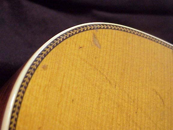
Below pix of the serving tray ready for the finish of
sealer and clear coats of lacquer. I call this serving tray the D-28
Herringbone since Martin Guitars used the herringbone wood purfling on their
D-28
Herringbone guitars.
The serving tray sides are centered onto the base, however the camera
angle made the front of the base appear to be wider! I like the
thinner sides and base of this serving tray versus the first one I did
because to me, it has more eye appeal and weighs much less with the thinner
wood.
Web published updates by Bill aka Mickey Porter on 07-27-16, 07-28-16 and
07-29-16.
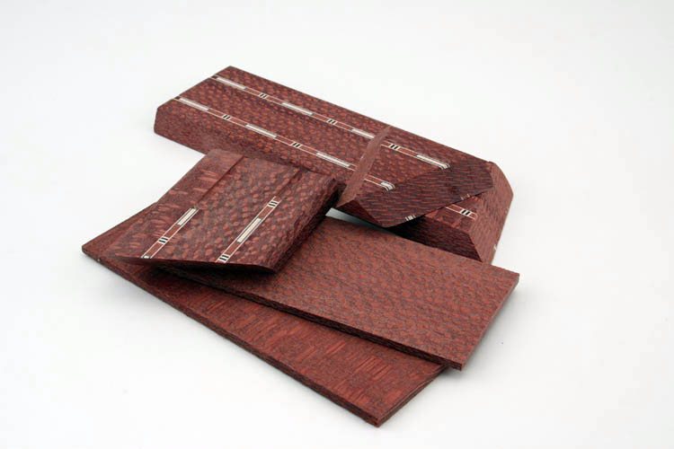
SCRAP CUT-OFF PIECES USED - LACEWOOD
Jerry Neal Adcock, one of my Brother-in-Laws who does some woodworking,
gave me a piece of
Lacewood a couple years ago and finally got around to
using it.
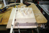
Pix below of the Lacewood scrap cut-off pieces from a "candy dish"
which is under construction:
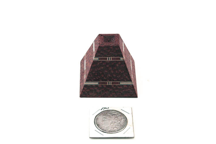
I will post a pix later when the Lacewood candy dish aka bowl is finished. Lacewood is
very, very dense and prone to chip out due to the complex grain structure even with sharp tools. The above
type of small
truncated pyramid SN 60 will
make a pretty desk paper weight. Vintage US silver dollar used as a
size reference. There definitely isn't enough room
inside this truncated pyramid for a
Royal burial chamber unless it is for a queen bee or ant.....grin if you must!
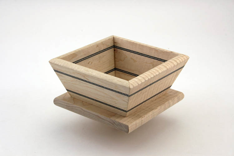
CANDY DISH SN 57
I have been making a couple fourteen inch square serving trays and/or
fruit bowls using curly maple and using the end cut-offs to make a small
six
inch square candy dish. Pix of one of the candy dishes in curly maple:
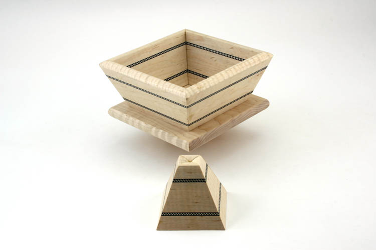
CANDY DISH SN 59
Below another curly maple candy dish SN 59 with the scrap cut-off pieces in the
shape of a truncated pyramid SN 60:
Web page updated by Bill aka Mickey Porter on 08-19-16.
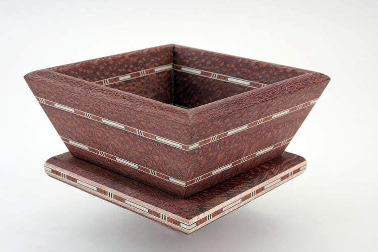
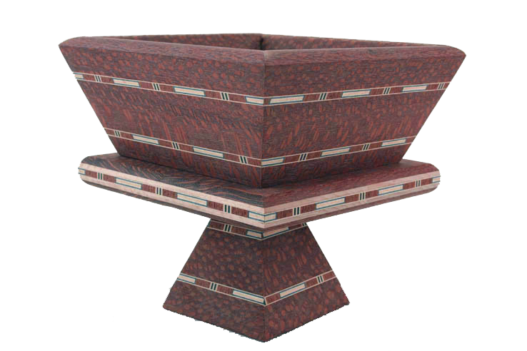
LACEWOOD CANDY DISH SN 61
I finished the Lacewood candy dish on 08-20-16 and had just enough wood
to finish the base, however I had to laminate a three ply base using a 3/16
inch strip that I ripped from the 1 inch thick board initially to reduce the
surface plane
time. This piece of Lacewood was very brittle, hard and prone to chip
out even with sharp tools due to the complex grain structure which is fairly
normal. I installed a
couple 1/4 inch diameter dowels in each miter joint for additional strength
since end grain wood glued is not that strong.
The dowels worked better than the size 0 biscuits of which the biscuits swell
pretty fast by design once glue is applied and hard to get the sides in perfect
alignment once the glue takes over. I used about nine or more very large rubber bands to apply pressure to
the sides and had the thing bound up with the rubber bands as if the candy
dish was going to be mummified.....grin if you must!
I mitered the ends of the wood marquetry aka wood purfling on the base
for more eye appeal and also centered the wood purfling into the curly maple
3/8 inch thick core used. A 3/4 inch bull nose router bit was used to
round over the top and bottom edge of the base with a single pass to make it
appear thinner since it was about 7/10s of an inch overall thickness with
all three laminations. I used a couple # 0 biscuits to join the maple
core. The width of the base is 5.5 inches and that was cutting it
close since the width of the Lacewood board was around 2.75
inches.
Below pix of the candy dish sitting on top of the small truncated
pyramid:
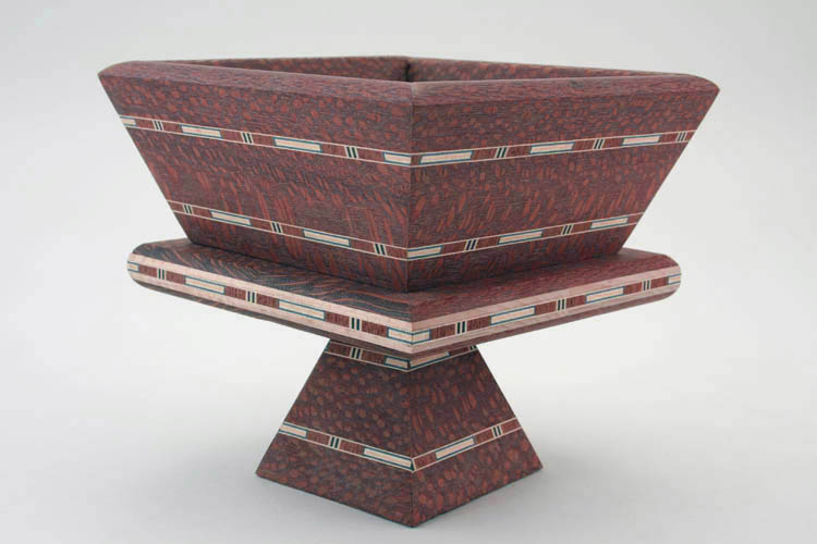
My bride has dibs on this candy dish and the small truncated
pyramid......grin if you must! The Lacewood reminds me of South
American
Snakewood but is not as dark in color and
as dense. Below the same pix as above but playing around with
PhotoShop CS2 learning how to make a transparent background for web
publishing.....thanks to
Ken LeVan of Shunk, PA for his technical
assistance.
Below scrap pieces from this project:
I think I have made all the serving trays I want to at this time and will
wait until the humidity level is low with the wind calm and start spraying
them with a sealer followed by a few coats of musical grade instrument
lacquer.
Web published update by Bill aka Mickey Porter on 08-20-16.
SANDING SEALER APPLIED
The humidity was down to thirty-eight (38) percent this afternoon and
applied a coat of sanding sealer to the serving trays. If the humidity
is still low around 7 PM, I will buff the items down using a well worn green Scotch
Brite pad and apply the first coat of lacquer. I coated all the above
items with a generous application of sanding sealer using Deft sanding
sealer from a spray can and probably used 1/2 to 3/4 can which is an
excellent product for short run applications. I wasn't in the mood to
bring out the spray gun, etc.
The fourteen inch square serving tray on the right has the best looking
curly maple wood pattern. My bride will get her
"pick of the litter" but she already has dibs on the
Lacewood candy dish and the matching truncated pyramid.
Border Maple Specialties owned by Dustin
Hensley in Gray, Kentucky has excellent kiln dried Appalachian curly maple for sale via
EBay and highly recommend his products and fast efficient service.
Dustin also has a
Facebook page.
Web published updates by Bill aka Mickey Porter on 08-22-16 and 08-24-16.
LEAVING ON A
SPIRITUAL NOTE
If you do not know Jesus Christ as your Lord and Savior, please take
this moment to accept him by Faith into your Life, whereby Salvation
will be attained.
Ephesians 2:8 - 2:9 8 For by grace are ye saved through
faith; and that not of yourselves: [it is] the gift of God: 9 Not of
works, lest any man should boast.
Hebrews 11:1 “Now faith is the substance of things hoped for,
the evidence of things not seen.”
Romans 10:17 “So then faith cometh by hearing, and hearing by
the word of God.”
Open this
link about faith in the King James
Bible.
Romans 10:9 “That if thou shalt confess with thy mouth the
Lord Jesus, and shalt believe in thine heart that God hath raised him
from the dead, thou shalt be saved.”
Open this
link of Bible Verses About Salvation,
King James Version Bible (KJV).
Hebrews 4:12 “For the word of God is quick, and powerful, and
sharper than any two edged sword, piercing even to the dividing asunder
of soul and spirit, and of the joints and marrow, and is a discerner of
the thoughts and intents of the heart.”
Romans 6:23 “For the wages of sin is death; but the gift of
God is eternal life through Jesus Christ our Lord.”
Romans 3:23 “For all have sinned, and come short of the glory
of God;”
Micah 6:8 “He hath shewed thee, O man, what is good; and what
doth the LORD require of thee, but to do justly, and to love mercy, and
to walk humbly with thy God?”
Philippians 4:13 "I can do all things through Christ which
strengtheneth me."


