ASSEMBLING THE BANJO
AKA SET-UPWith some down time on my hands waiting for the neck and resonator finish
to cure out about a week before I do another wet sanding and continue with
the last build up coats of lacquer, I decided to get the banjo "pot" assembly
together. It is very easy to understand why Gibson had a FON (Factory
Order Number) system followed by the lot number for their banjos since after
all the parts are pre-fitted prior to applying the stain, color and finish;
e.g. tone ring, wood rim, neck and flange, it would be nearly impossible to
keep the parts together matching even with the number stamped on the wood
rim, resonator and neck heel since it is to my understanding there were
never any FON's on tone rings.
With our current advancement in CNC machines and other robotic processes,
many manufacturing facilities have a production line of simply picking a
part from a bin and all the parts will fit together with accurate precision.
It was Eli Whitney in 1798 who was probably the first one that
invented a way to manufacture muskets by machine so that the parts were
interchangeable. Ironically, it was the manufacturer of muskets that
Whitney finally became rich and not from his Cotton Gin invention....well, I
strayed from the banjo assembly....grin if you must!
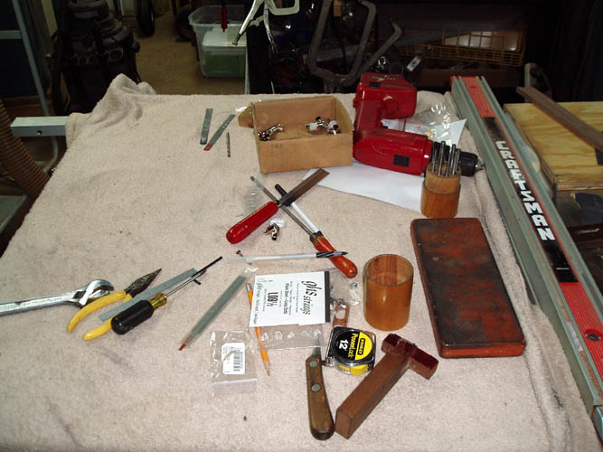
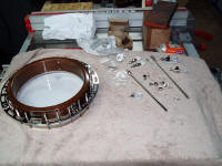
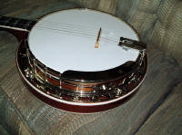
POT ASSEMBLY
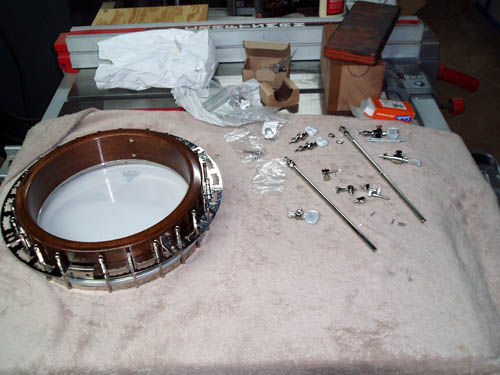
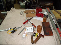
While assembling the banjo pot assembly you need to protect the parts by
using some means such as a piece of carpet, cloth or towel over your work
bench and with working
space at a premium, I used a corner of my router table as a working station
which I know is Rube Goldberg for sure. I later regrouped to my
multi-purpose saw table with a bar stool for a little more comfort. The Great Depression Era tube
and plate flange banjos, most of the tubes would stay attached to the wood
rim when you removed the L brackets, plate, etc. and would literally snap into the groove
machined into the wood rim and not because the tube was out of round either. The wood rim that I had Jimmy Cox manufacture for
me would do the same thing after the finish was applied and the satin finish
on the wood rim reminded me of the pre-war ones. Out of habit, I gave
the wood rim a thump from a middle finger knuckle to see if it still gave a
clear bright pitch after the finish of which it still did and I felt good about
that since I have knuckled some wood rims that were more or
less muted giving a very dull type "thud" sound and a fair indicator that the completed banjo
would not be a
corker! A few pixs below:


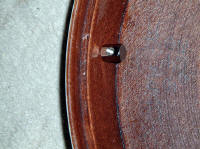
The Kulesh Gibson USA flathead tone ring serial number 7236 which came
out of a Gibson banjo of which my friend stated that it sounded better than
the new high dollar tone ring the owner had him install was placed on the wood rim first and aligned the
neck hanger bolt hole up with the 3/16 inch diameter hole drilled in the
wood rim and it was a perfect match and used the drive pin punch to align
it. The tone ring fit just a little tad tighter than I like due to the
thin build up of finish on the side of the wood rim but I don't think it
will be too tight to cause a problem. My ideal tone ring fit is one
that you can remove with your hands but when the wood rim and tone ring are
inverted, the tone ring will not fall off the wood rim by
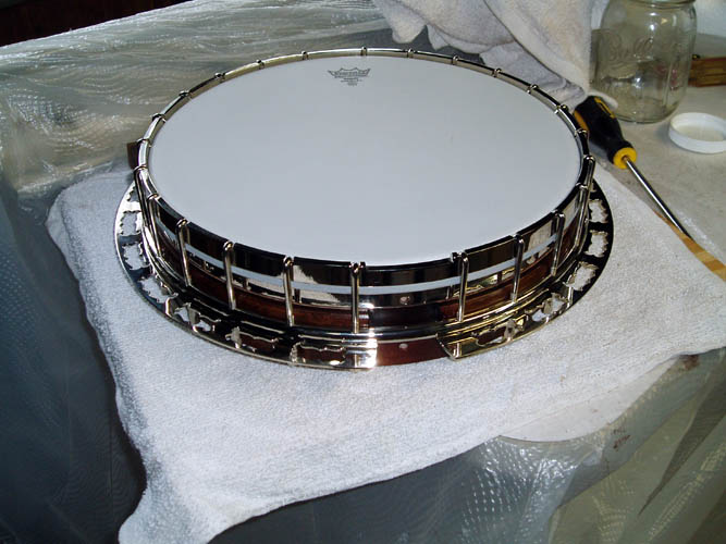
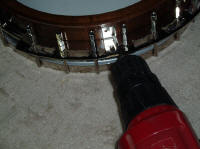
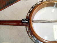
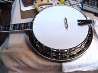
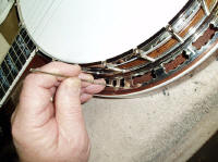
gravity alone! The tube portion of the flange
snapped into place as evidenced by the first picture and that brought a
little smile too my face since most of the pre-war ones did the same thing.
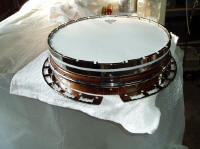
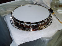
The medium crown Remo head was centered onto the tone ring
and the notched tension hoop was placed on the head and trying to keep the
notched portion where the neck heel fits against centered between the wood
rim neck hanger bolt holes (east/west orientation) of which I had to make
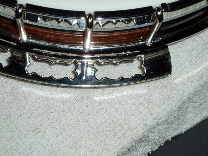
two attempts to get it right. The special Porter Flaming Claw
flange was also aligned with the hook holes of the tube and tension hoop and
each hook was inserted and the nut installed only finger tight.
I used a set of pre-war replica nuts that I had Waverly Musical Products
manufacture for me when they were in New York long before Stewart MacDonald
bought them out and believe I was the first
mail order company in the early 1970s to offer those exact reproduction
pre-war nuts to the banjo community.
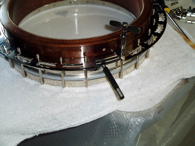
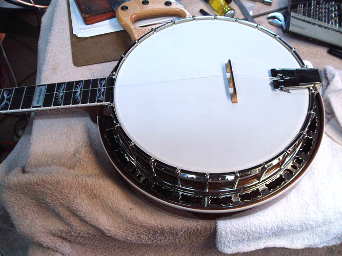
With all the
hook and nuts finger tight, the pot assembly was turned
upside down and this is where the fun begins to get the head brought up to
the proper tension with the
tension hoop being the same height above the head
all around the perimeter of the tone ring and the tension hoop neck notch
flush with the top of the head. There have been volumes of articles
published on how to install the head and tune it along with special tuning
aids and devices to sequence the tightening which will get you in the ball park. I don't profess
to be an expert and I haven't installed and tuned a head from "scratch"
since around 1978 but I do have some friends that I can call upon who will
get it set-up professionally if I am not satisfied with my own set-up.
Each banjo has it's own unique voice and takes time and effort to find out what
particular set-up will get the most out of your banjo that meets with your
approval. Some are winners and some are not; it can go either way,
especially on a new banjo being brought to life for the first time without
the benefit of the cells in the wood rim to crystallize brought about by
mother nature; (time) and usage!
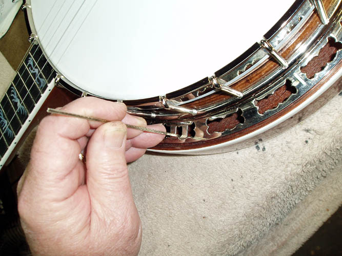
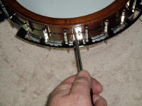
My goal at this point is to equally tighten all the nuts and the keep the
head tension about a G pitch and let it settle in. I tightened the
nuts by feel only and used the tips of my thumb and fingers while turning the nut
wrench not to overly tighten them. A good rule of the thumb is to turn
each nut only about 1/6 a turn when you have them finger tight, otherwise
you will end up with unequal tension when you work your way through the 24
nuts to tighten with a tension hoop not parallel to the head.
Each component you add to the pot
assembly such as neck, bridge, tailpiece, strings, etc. will have an effect
on the tone, volume and timbre and I plan to go down the "middle of
the road" using those components that are known producers,
whereas price and name brand endorsements are not the determining factor!
Heck, Earl Scruggs could make a Kay or Harmony banjo sound like Earl
Scruggs, yet I would sound like dung on his or any other pre-war flathead
Granada......grin if you must!

Today is November 2, 2010 and had some down time from hunting and decided
to mess with the banjo a little bit this evening after doing my Patriotic
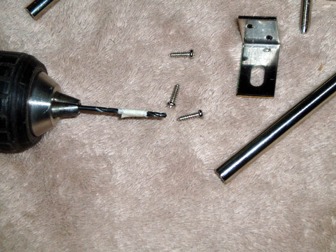
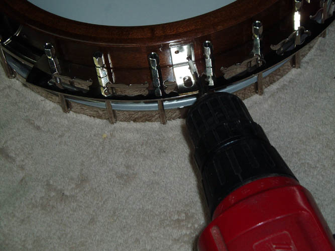
duty of voting. I installed the resonator
L brackets a couple days ago
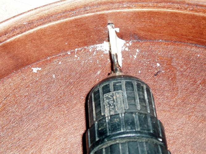
and will insert some pixs. On the hard maple wood rim, it is best to
pre-drill the screw holes for the L brackets and I normally measure the body
portion of the screw and then take a reading of the overall diameter
including the screw threads and will drill the pilot hole to the smaller
body portion of the screw and that is more than enough to hold the L
brackets in place. Gibson placed the L brackets on the Mastertones
centered on the third (3rd) tone hole from the neck heel and also the same
from the tailpiece which placed them in quadrants about equally spaced and I
followed suit as well. I taped the drill bit the length of the screw
of which there is plenty of room on the wood rim not to drill through but
you never know; it certainly is possible if you go "brain dead" while
drilling and you have more than 3/4 inch drill bit extending from the drill
chuck....grin if you must!

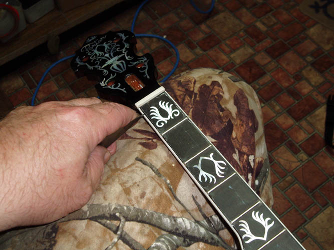
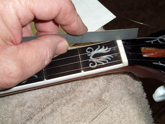
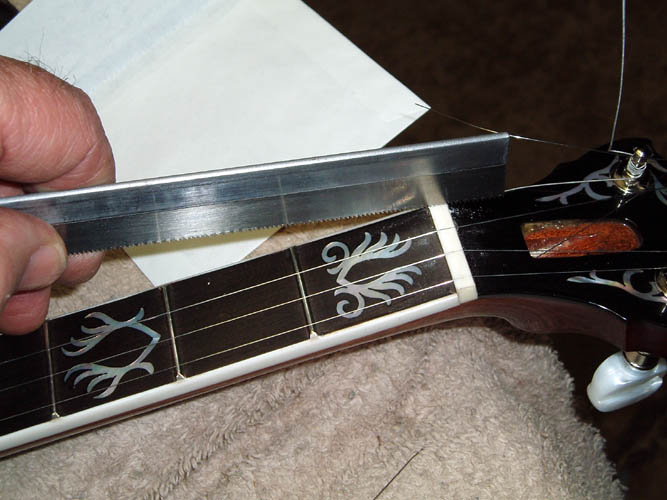
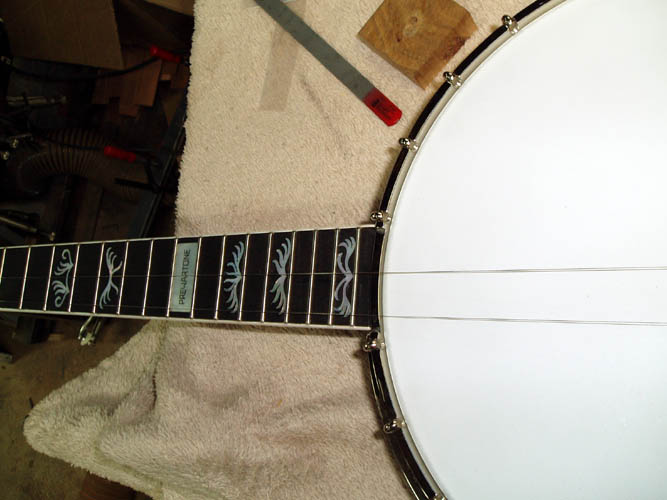
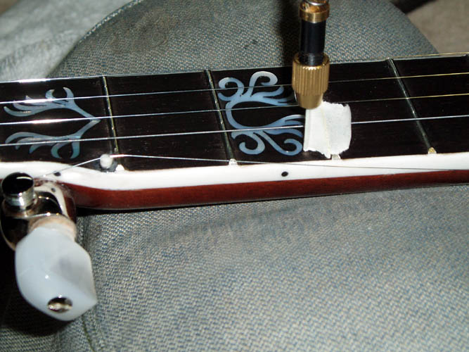
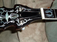
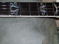
CLEANING THE FINGERBOARD
I removed the masking tape from the fingerboard and scraped the lacquer
that had leaked under the tape and I left a small portion of the fingerboard
exposed to the finish to prevent and lacquer chipping from the binding which
can happen when removing the masking tape. It is best to use a good
automotive pin stripping tape since the regular "Wally World"
Elcheapo tape
leaves a mess from the adhesive used on the tape. Naturally, I used
the Elcheapo tape and there was a little extra effort to remove it from the
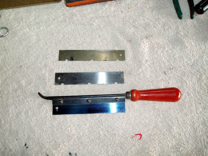
fingerboard. There is no rocket science in cleaning/scraping the
fingerboard and I used a small utility knife and 0000 steel wool. The
fret board was level and fret ends didn't need any additional work, however
if the fret board needs leveling, now is the time to do it followed by
crowning and dressing the frets. Stewart MacDonald has an assortment
of excellent tools specially designed for this purpose. Pixs
below:
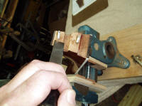
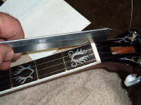
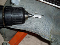
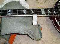
5TH STRING NUT INSTALLATION
I have drilled many
5th string nut holes totally freehand by eye without
a fixture and don't recall having a problem but that was way back when and
my woodworking skills were very fine tuned and had good eye hand
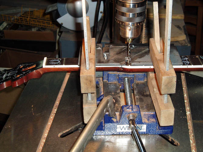
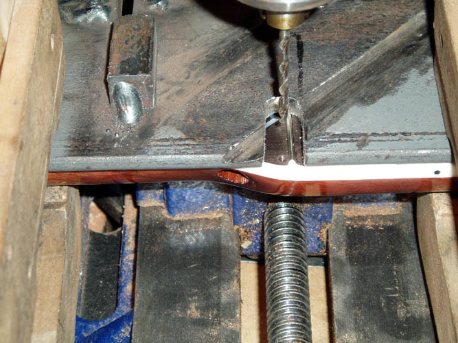
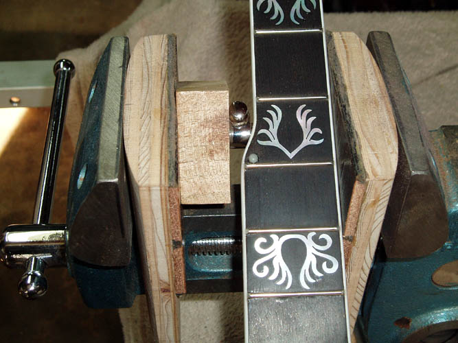
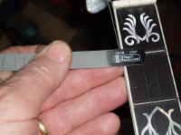
coordination. However, I decided to make a simple jig for drilling the
5th string nut and found a piece of 3 inch by 8 inch x 1/4 inch thick
channel angle iron that was once part of some type of fixture for my
tree stand manufacturing and only had to drill a hole and saw a couple
connecting slots
in one side of the angle. The angle was then placed in a small vise
and the neck aligned under the slot where the hole will be drilled next to
the 5th fret. You could go a little high tech and install a drill
bushing and a couple locator stops if you were on production. Pixs below:
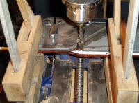
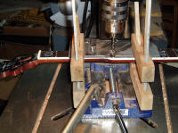

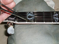
With the 3 inch channel iron, there is plenty of room underneath to clamp
the neck to the angle using cork padded guitar makers clamps. The slot
is large enough to allow you to see where the hole needs to be drilled and
keeps the neck parallel and square to the drill bit. The frets rest
against the back of the channel iron, therefore it is not necessary to pad
the fingerboard area. I have a cheap milling vise but there was too
much "slop" in the movement and didn't have the time to adjust it out so
opted for the small vise. It is a dawg to align and took several trial
and errors to get it right....most people install the 5th string peg which
can be from 1/8 to 5/32 or more in diameter and you can go elaborate with a
stepped bullet shaped head which I have seen on some of THE GREAT
DEPRESSION ERA banjos or just simply use a straight diameter 5th
string peg. I went the easy route and purchased a pre-manufactured 1/8
inch diameter x 1/4 inch length bleached bone 5th string nut and got a good
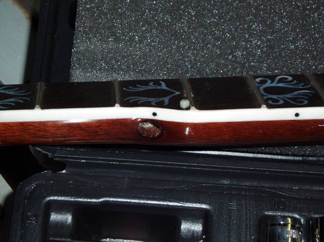
chuckle while installing the 5th string nut. After drilling the hole
to 1/8 inch in diameter about 3/16 inch deep, I placed the bleached white
5th string nut down onto a solid white cutting board and when I came back to
retrieve it, my State eye plan glasses could not locate said 5th string nut.
I figured it must have rolled off onto the floor and got down on all fours
and could not find the little "bugger". I dug out a piece of
unbleached bone nut material and sawed a strip out of it and chucked it in
the drill press and made one by rounding it with a file. I left a
slight step from the 1/8 inch diameter portion that is recessed into the
fingerboard although it wasn't as pronounced as some of the pre-war ones.
After installing the 5th string nut, there was the original 5th string nut
as plain as day on the white cutting board and I had a very good robust
laugh to myself. I glued the nut in with some Epoxy 330 colored with
Mohawk black powder and will let it dry before proceeding any further.
I prefer the 5th string resting on the nut rather than the 5th fret.
Note: On 11-12-10, I had the neck on the pot assembly and
noticed the 5th string nut placed the 5th string way too close to the 4th
string and had to grind it out of the fingerboard with a small carbide end
mill and re-drilled the hole closer to the fingerboard binding and glued in
place with Epoxy 330 with a black coloring powder and it was much better.
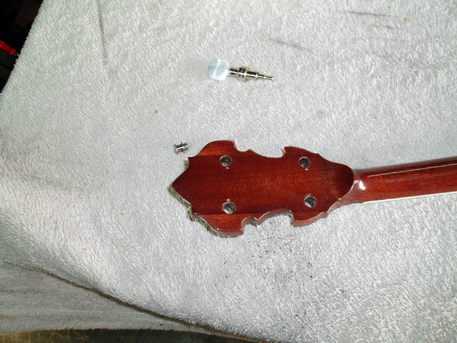
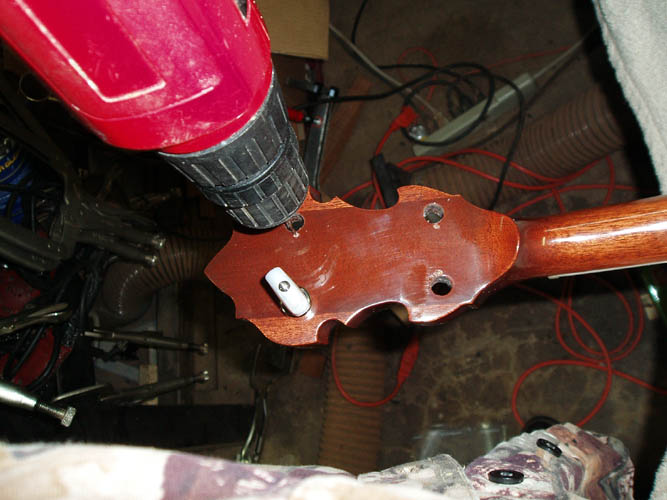
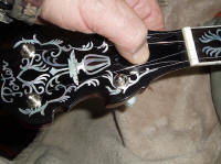
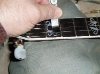
INSTALLING THE GEARED PLANETARY TUNING MACHINES

There usually is a good build up of lacquer in the peghead tuner holes
after the application of all the coats of finish and needs to be cleaned out
with a reamer the appropriate size or use a standard round chain saw file
which works very well. Care must be taken when filing since the
lacquer is very brittle and prone to chip on the opposite side of your
filing if you get in a hurry and angle the file to hit the opposite side.
You can also remove the lacquer build up with the Dremel tool and router bit
and/or sanding drum but it is easy to scratch the peghead finish if you use
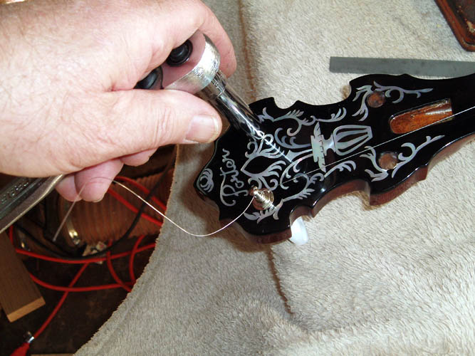
a router base and works better freehand if you are steady enough. After the tuner holes were cleaned out, I installed a
tuner in each hole and aligned the tuner where the small "locking
post" that protrudes from the tuner housing was positioned toward in
inside of the peghead and pressed into position to make a witness mark for
drilling a relief hole about 1/16 inch in diameter and about 1/8 inch in
depth. Many simply install the tuning machines without pre-drilling a
pilot hole in soft woods such as Mahogany but it is safer to pre-drill the
pilot hole and mandatory for hard woods such as maple. It is
best to use a socket or nut driver to tighten the hex shaped threaded
bushings to prevent marring the peghead finish as it is easy for a wrench to
slip. Do not overly tighten each tuner threaded bushing and make
certain the washer is orientated with the flat surface down and the taper
surface of the washer up. I planned on installing a set of Schaller D tuners for the 2nd and 3rd
strings but decided at the last moment I really didn't need them since I
haven't played any in over 32 years on the ole 5-string and need to get some
basic stuff down again and had to order a couple Stew Mac's
5 Star Planetary tuners. Sometimes the addition of the heavier
Schaller or Keith D tuners adds more mass to the weight of the neck and
helps the banjo sound and it goes the other way sometimes as well!
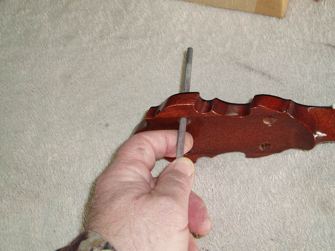
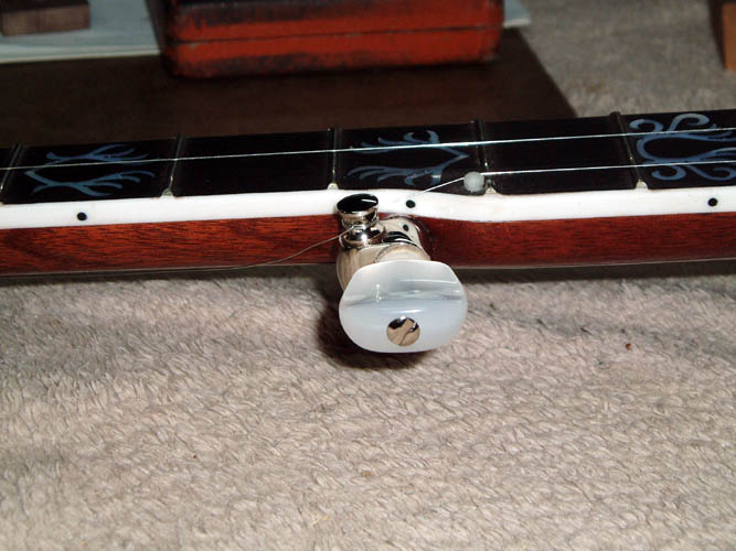
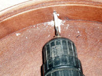
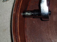
5TH STRING GEARED PEG INSTALLATION
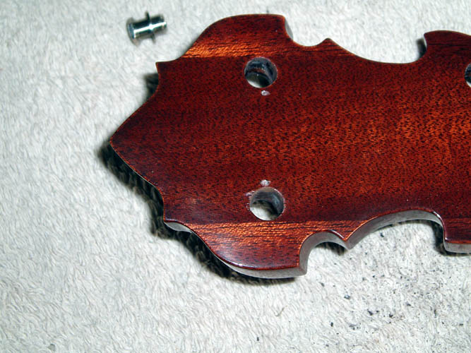
My first step was to ream the 5th string peg hole out using the tapered
hand reamer. All I wanted to do is remove the build up of lacquer
since the tapered hole was already predrilled before finishing.
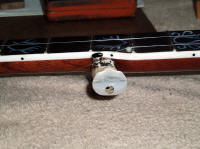
Instead of driving the 5th string peg in, I used the Shop Fox Parrot vise
with my home made tapered padded (self aligning) jaw inserts and used a wooden block with a
3/16 inch diameter hole drilled in it to keep pressure on the geared 5th string peg main
housing instead of directly onto the shaft/internal gears and simply turned the vise handle
pressing into position the geared 5th string peg but you have to be careful of the pressure generated and know when to stop
or "bottom out". After installing the Schaller geared 5th peg,
I
noticed some lacquer did chip from around the pre-drilled tapered hole edges which
was not very unsightly and fairly common as well. You want to angle
the 5th string post/housing toward the 4th fret with the top of post
top nearly level/flush with the fingerboard to prevent any interference and
give the proper downward string angle from the 5th string nut to the 5th
string peg post.
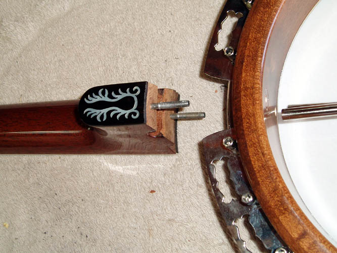
FITTING THE NECK TO THE POT ASSEMBLY
I didn't take a step by step pix of fitting the neck to the pot assembly
since I got all wrapped up in what I was doing...it was simply just too much
fun and didn't want to break the rhythm....grin if you must! The neck
lag screws were inserted into the pot assembly and a flat washer next to the
wood rim and both coordinator rods were tightened securely with the aid of a
punch and small nail.
I positioned the bridge on the head for the 26 3/16 inch length scale and
placed a straight edge from the top of the bridge to the nut to check the neck fit and see how close I was using a 11/16 inch
height bridge and the neck set was about 3/16 inch high above the 12th fret
and string of which I was opting for around 1/8 inch with zero tension on
the wood rim from the
coordinator rods although many individuals make minor
adjustments to the action as Gibson advocated back in THE GREAT
DEPRESSION ERA catalogues but I don't agree with it since some take the
word minor meaning more than 1/16 inch. I personally
prefer no distortion of the wood rim whatsoever other than the stresses
inherent by the normal interaction between the tone ring, wood rim and
components necessary to keep tension on the head.
It took several attempts to get the action lowered and had to trim just a
little off the lower portion of the neck heel and adjust the slight taper of
the upper portion of the neck heel and did so by using a small utility knife,
wood chisel
and a Dremel tool with a 3/4 inch diameter sanding drum with about an 80
grit abrasive sleeve and took my time and checked after each adjustment
until it was close enough to start slotting the nut. Most of the
pre-war necks before the RB75, RB7, 12 and 18 had their adjustments done
with wood chisels and the persons doing that element of production was
definitely a Master fitter for sure....it is amazing how accurate those
necks fit the wood rim. This neck has a slight cant to it whereas the
3rd string is to the left of center line (axis) and will correct the heel axis fit a
little later. I will probably take out the hanger bolts and set up the
heel sanding fixture and adjust the position of the neck onto the fixture
for a proper 3rd string center line alignment.
NOTE: I took the neck off the pot assembly on 11-20-10 and
used a Dremel tool with a 1/2 inch diameter sanding drum/sleeve and took
enough material off the right hand portion of the neck heel without removing
the hanger bolts and corrected the neck axis to where it needed to be.
You can use the coordinator rods as a reference since the neck will be
centered and in line with the coordinator rods when viewed from the rear of
the pot assembly but the real "acid" test is how the 3rd string orientates
down the neck especially from the 7th fret to the 22nd fret which should be
centered of which the tailpiece is centered and the bridge in a natural
static position; i.e. ( without having to slide the bridge east to west orientation
to get the strings centered on the neck). I have a slight space .010
inches between the end of the fingerboard to the tension hoop which should
be nearly flush for better eye
appeal (IMHO) with at least .001 clearance for maximum transfer of neck
vibrations to the pot assembly but it doesn't seem to inhibit any volume at
this point but this is not the ideal set-up for sure as far as eye appeal, although open for
debate. If I decide not
to fine tune the heel fit to make the fingerboard flush, I could easily add
a very thin .010 inch black plastic shim between the end of the fingerboard and the
tension hoop but don't see a need at this point. The ideal fit
of the fingerboard to the tension hoop is having at least .001 clearance,
whereas the
tension hoop can be removed without loosening the coordinator rods.
Most of the pre-war Mastertones had the end of the fingerboard gently
touching the tension hoop or just a minute clearance less than .003.
It is imperative that the neck
heel fits completely flush with the wood rim with a little clearance around
the flange; whether it is a two-piece or one piece flange and there is at
least .001 clearance between the end of the fingerboard to the tension hoop.
If the end of the fingerboard is binding against the tension hoop and there
is a gap in any part of the neck heel fitting to the wood rim, you do not
have the optimum or maximum transfer of energy or vibrations which is a bad
thing. Again, the 3rd string should be centered between the 7th fret
down the neck thru the 22nd fret, whereby the bridge will be naturally
centered on the head without having to force the bridge either right or left
of the true axis or center line. The truss rod installation is
not the true axis or center line
of the neck in relationship to the pot assembly for a 5 string banjo but it
is for a tenor or plectrum banjo.

ATTACHING THE TAILPIECE
I am using a post-war
Presto tailpiece which seems to be the right
balance between mass and function and is attached to the tailpiece bracket
from the lower coordinator rod using a bolt and nut. Normally, the
tailpiece is sitting on the tension hoop or slightly above and held in place basically by
string tension only. The adjustment screw was removed from the
tailpiece and the height adjusted so as to "float" with about a 3/16 inch
gap between the front of the tailpiece from the heat...might be a little
more. Since I am using the two piece flange
instead of the one piece flange, the tailpiece bracket is of a shorter
length but on this particular reproduction tailpiece bracket, it was too
short and had to drill an extra hole toward the outer surface to allow the
tailpiece to properly align. I will replace the tailpiece bracket at a
later date or make another one out of stainless steel flat stock.

SLOTTING THE NUT
As I stated earlier, I did not want to use the Schaller D tuners,
therefore I basically only fitted the 3rd string which more or less is
centered down the fingerboard from the 7th fret through the 22nd fret and at
this stage wanted only to get the neck action in the ball park and I will
use the
light GHS J.D. Crowe
PF140 signature set strings which are .0095,
.011, .012, .020 and .0095 to start with and might go to the PF135 if
necessary.
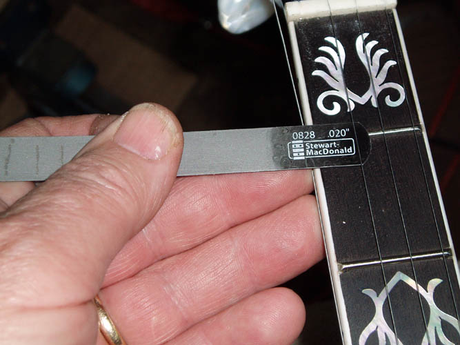
I roughed in the string slots in the nut using the .010 small
gauged saw from Steward MacDonald and the nut width with binding
installed was right at 1.250 inches and the spacing was about .157 from the
outer binding for the 1st and 4th string and the 2nd and 3rd string equal spacing
of about .312 inches. The initial nut slotting left the strings very
high off the 1st fret and when my other tuners arrive will get them around
1/32 to .020 inch or less off the 1st fret with the action of which will be on the
high side. Some set-up persons check the nut/string action by
depressing a string at the 2nd fret and observe how much clearance between
the bottom of the string depressed at the 1st fret and there should be just
enough clearance to see daylight between the top of the fret and the bottom
of the string. It takes time to fine tune the depth of the string slots but
not easy to correct if filed too low and usually requires the installation
of a new nut and certainly don't want to do that! Seems like way back when I used jewelers saw blades which
were pretty close to the width of the strings when slotting the nut and this
time around used the .010 thick gauged saw from Stew Mac of which 1/2 of a thousand overage shouldn't
make that much difference in the string slot in the nut and did purchase a
couple other nut files and they had one that was .020 inch in width which
will be perfect for the 4th string and will have to "wallow" out the 2nd and
3rd string nut slot for a proper fit. I only installed the 2nd and 3rd
regular 5 Star planetary tuners to check the action along with the 5th
string. Back before Stewart MacDonald offered gauged saws, some of the
old time musical supply companies that supplied violin parts and some of the
German companies offered Luthier tools and supplies of which I purchased
what was available and made the balance that was not available.
NOTE: Most of the prewar nuts were only 1/8 inch in width
whereas most modern builders and factories utilize a 3/16 inch width nut.
The nut on this banjo tapers from the leading edge abutting the fingerboard
approximately the same angle of the peghead and imperative that you taper
the string slots in the same relationship and avoid the string riding high
in the slot away from the leading edge of the nut, otherwise the intonation
will be off from the first fret to the nut.
When the tuners arrive, I will take a few pixs slotting and filing each
string slot to the proper depth. At the moment the slots are not deep
enough and will have to trim the top of the nut down once the proper string
action is reached where a little over 1/2 of the string diameter is resting in
the nut slot. To me it has more eye appeal than a lot of nut
exposed above the strings.

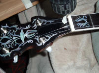
I did notice that the tension hoop was
not perfectly centered or the tube and flange but will leave as is to see
what the thing sounds like. I will probably have to do a little
tweaking on the wood rim lag bolt holes since the neck is not perfectly
level with the tension hoop although the tension hoop appears to be parallel
to the tone ring, etc. The head tap tones about a G note and will
increase the tension to G# as most like that tension for a flat head tone
ring. I also observed that the neck axis is off a little and thinking
back when I made the Rube Goldberg heel radius sanding fixture, I forgot
that the 3rd string should be aligned with the center of the fingerboard
from the 7th thru the 22nd fret and aligned the neck onto the sanding
fixture centered at both ends with the truss rod of which you have to split
the difference between the truss rod center and the 3rd string location at
the nut. Oh, well, my bad on that
one; that is why you pay good bucks for a neck made right the first time from
someone like Frank Neat. I moved the tail piece over enough to compensate for it but that
is not fixing the problem and doesn't place your bride in the center of the
head east to west. Reshaping the heel by hand is a trial an error
procedure and takes patience and good eye hand coordinator and I have
already worked on it a couple times and it is getting closer but still a
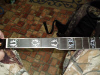
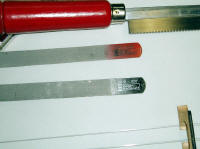
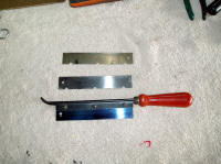
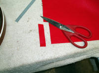
ways to go. The bottom second pix is a fret and slotting saw with
different thickness blades and about 40 years old made in West Germany and
still going strong....that was back before StewMac started adding their
specialty tools for sale.
NOTE: Corrected the neck axis on 11-20-10.
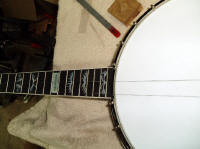
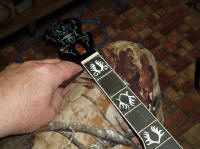
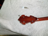
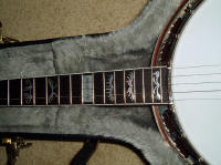
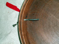
I had a tremendous laugh this evening (11-09-10) while talking with my
Sister in Reidsville, NC as I related to her that I only had two strings on
the banjo waiting on my tuners to arrive and she stated, "Brother, that is a
Redneck banjo for sure"....we nearly
tore a gut out laughing.....grin if you must! See the above pix on the
right.
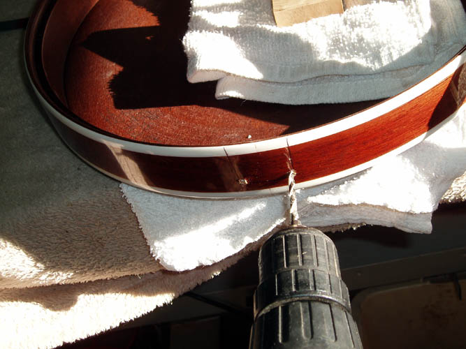
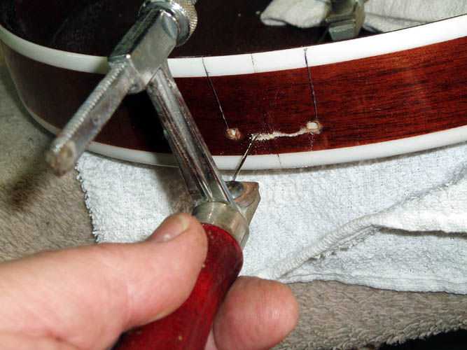
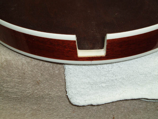
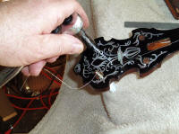
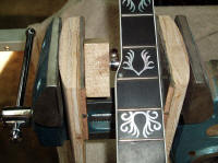
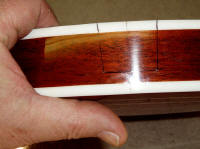
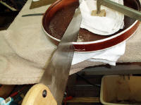
CUTTING THE RESONATOR NECK NOTCH
Some cut the neck notch before the finishing stage and others cut the
neck notch after the resonator finish is applied. I chose to mimic the
ole Gibson resonator by cutting the neck notch later and I believe Gibson
still does it that way today but could be totally wrong. I guess the
advantage with the notch already cut, you don't have to worry about the
lacquer chipping from the cutting process and if many coats are applied and
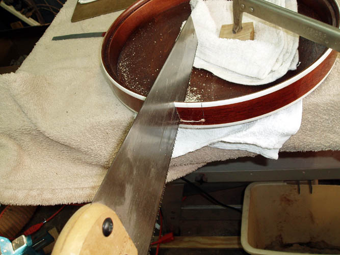
it is very brittle, chipping will occur. I used about as low tech
tools as there are being a jewelers saw blade of which the coping saw would
be better, and a straight back saw. I drilled a couple 1/8 inch
diameter holes at the bottom corner of the notch and inserted the jewelers
saw blade through one of the holes to make the bottom cut. I used a
wooden template to transfer the pattern and marked it in with a fine tipped
black marker. Score the line with a utility knife to help prevent the
lacquer from excessive chipping. I cleaned the saw marks up with a
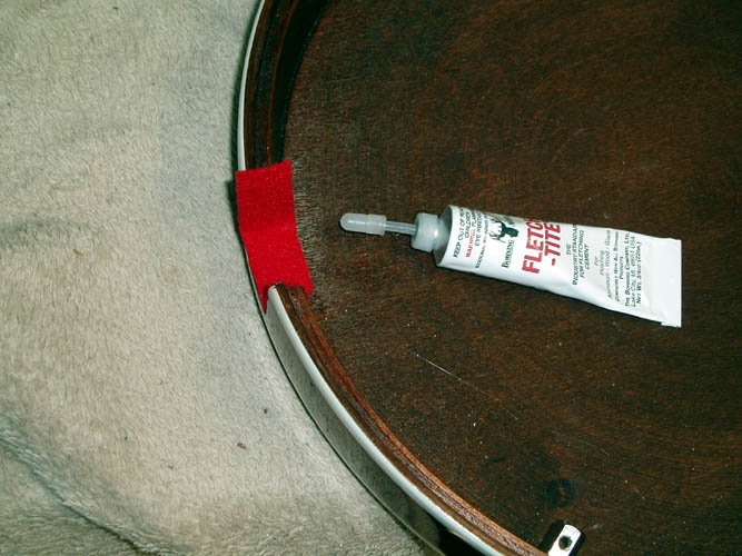
fine wood rasp and the only thing left to do is find me a piece of dark felt
at least 1/16 inch or more in thickness for padding to help hide the raw
wood edges from the saw cuts and protect the heel of the banjo. You
could make the notch on a table saw with a wide dado blade but you would
have a parallel cut instead of a taper as is on most of the banjo necks and
would require additional sanding/cutting. Pixs below:

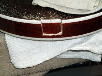
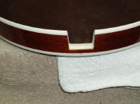

I rough freehand cut the felt for the neck notch and used Fletch-Tite to
glue it in place and will trim the inside to exact fit when dry.
November 11, 2010 by Bill aka Mickey Porter.
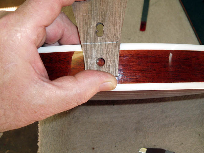
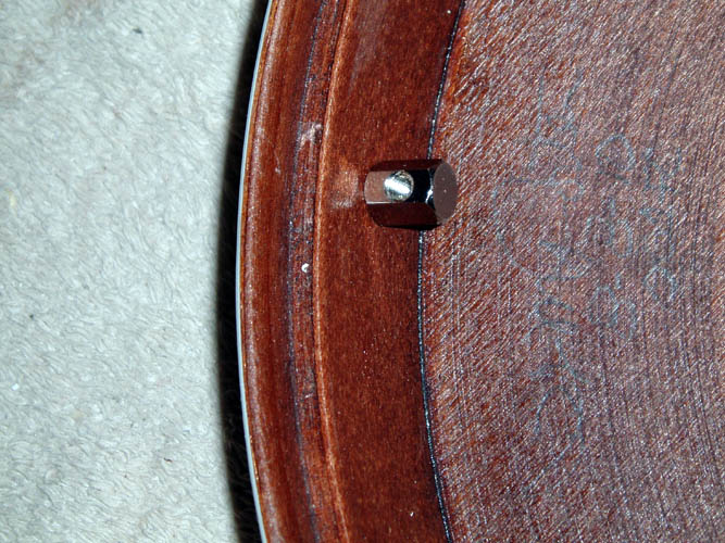
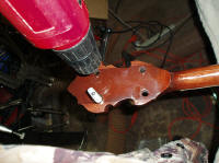
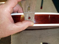
INSTALLING THE RESONATOR WALL LUGS
I placed the banjo pot assembly onto the resonator and scribed a mark
through each wood rim L bracket onto the resonator side wall to give me a
vertical witness mark for the location of the
resonator lugs. Most
Gibson style wall lugs are mounted about half the distance of the height of
the inside sidewall measuring from the rabbit groove......some builders
measure about 3/8 inch from the rabbit groove and have the top of the wall
lug positioned at that distance. If you want your resonator
thumbscrews to be in a vertical orientation, your wall lugs will need to be
in a perpendicular plane with the resonator outside wall instead of being
flush mounted with the inside wall since it is tapered. There is
enough room in the wood rim L brackets to allow you to mount them either
way. The
standard reproduction lugs have a diameter of .143 inches at the base of the
screw threads and the overall outside diameter is .192 inches and used a .140
plus diameter drill bit taped off for the proper depth to keep from
drilling through the resonator side wall. After drilling the pilot
hole, I used a 10-24 tap and hand started a few threads for the lug and used
a socket wrench to screw them in place. You can tap the threads in if
you desire but it is easy to strip them out installing the lugs. Pixs below:
INSTALLING THE TRUSS ROD COVER
Opps...I gave away the last small pre-war truss rod cover I had a few
years ago and don't have one or any black plastic material to cut one from
so will have to round one up!
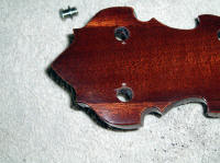
NOTE: Frank Neat of Frank Neat & Sons Banjos provided me
with several truss rod covers at no cost and very much appreciated.
Frank Neat is one Top Craftsman and a very genuine and giving person too!
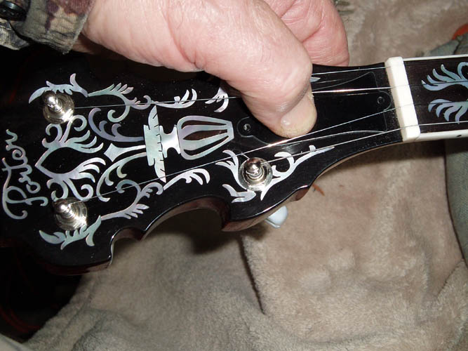
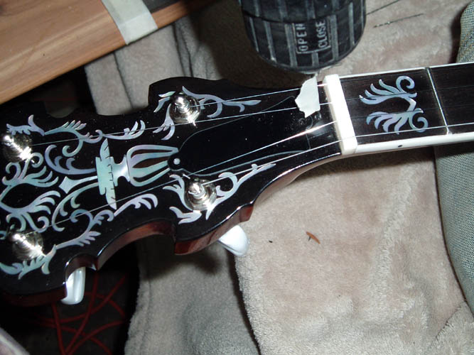
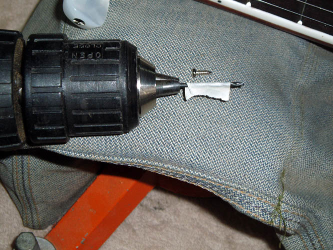
No rocket science on installing the truss rod cover. I found a couple
screws that were from 1/4 to 3/16 inch in length and the right size diameter
to fit the holes punched in the truss rod cover. I checked the screw
threads smallest diameter and needed a .070 drill to bore the pilot hole.
As usual, I marked the depth of the hole to drill with some tape on the
drill bit but you have to be careful since the tape can move up the drill
bit if you don't stop just shy of the tape. I just "eye balled" the
truss rod cover in position and drilled through the truss rod cover hole
into the neck peghead and used the shorter length (3/16") screw for the nut
area since there is not much material under the truss filler area and used
the 1/4" length for the upper screw. A few turns of the screwdriver
and fini. Pixs below:
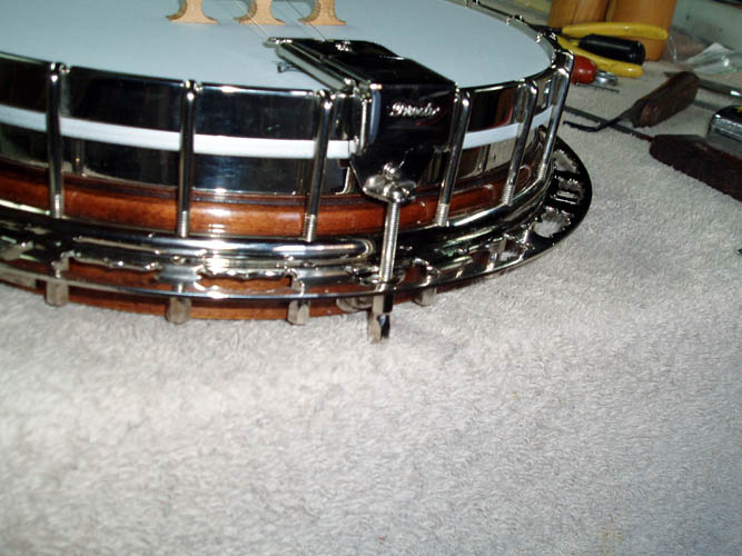
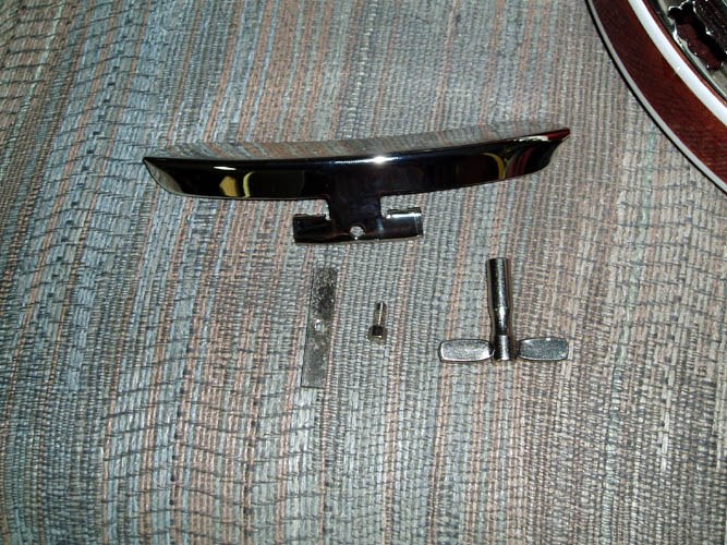
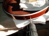
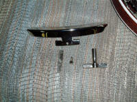
INSTALLING THE ARMREST
Installing the
armrest has to be the simplest and easiest aspect of banjo
construction with one single bolt to install. The rectangular mounting
bar is positioned behind two of the hooks, whereas the armrest lower bracket
has two notches formed to locate off the hook and the bolt which is 1/4 inch
hex. goes through the bracket and screws into the rectangular bar and
tightened enough to hold the armrest in position. The armrest I am using
is a copy of the old ones, however this "generic" one is made from .050
thickness brass which is way more flexible than The Great Depression Era
armrest but I guess it will be ok. Pix below:
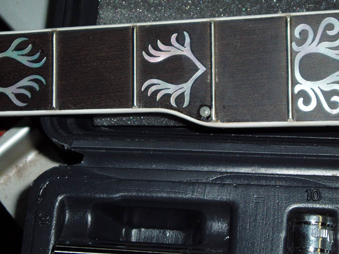
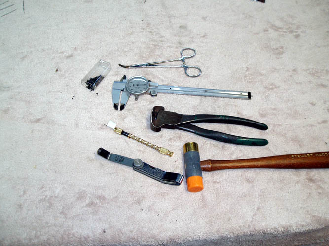
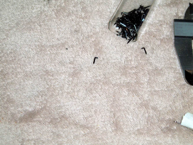
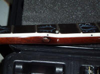
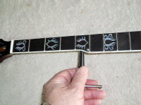
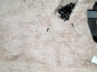
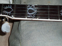
INSTALLING THE MINIATURE RAILROAD SPIKES
The miniature railroad spikes I have are about 1/4 inch in length and
.030 inches in diameter although not a true circle with one measurement
being .034 inches. The tools you will need are a micro hand push type
drill and a bit measuring .030 inches in diameter, flush cutting pliers,
curved hemostat, micrometer, feeler gauge .015, small hammer, masking tape,
fret crowning tool and small fret end file for final dressing of the spikes.
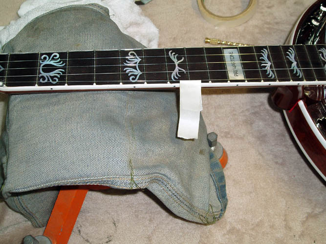
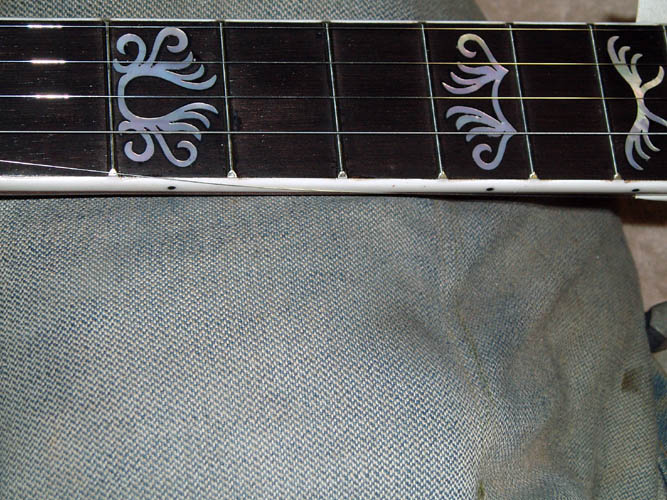
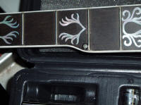
I installed the spikes at the 7th and 9th fret and the edge of the
inlay at the 7th fret was right where the spike needed to be so installed it
toward the 7th fret instead of centered between the 6th and 7th fret.
I lightly drilled a witness mark underneath the 5th string behind the 7th
and 9th fret, whereas you could mark the spot with a white lead pencil, etc.
String tension was removed from the 5th string and a piece of masking tape
wrapped around the 5th string and the string was pulled out of the way and
the taped to the side of the neck. The micro drill bit had a piece of
masking tape applied to mark the desired depth which was around 3/16 inch
and both holes were drilled keeping the little micro hand drill in a
vertical position. I used a padded rifle rest (sandbag) to
support the neck which was adequate for this job. The length of the
railroad spike was cut to around 3/16 inch and placed in the curved
hemostat and locked into place. The curved hemostats gives you a
means to hold the miniature railroad spike while lightly hammering it into
position. A feeler gauge .015 to .020 inch in thickness was placed
underneath the head of the spike and driven flush. I went back and
used the .015 feeler gauge to provide a little more clearance between the
top of the 5th string at the 7th fret. You can apply a drop of crazy
glue to the tip of the spike if you desire but if your drill bit is the
right size, there is no need but you might want the little extra bit of
security due to fingerboard expansion and contraction due to the humidity.
The miniature railroad spikes will break, bend, etc. and are very hard to
remove if you break one off in the fingerboard but there is enough room to
install one close by if that happens. You can cut shorten the head
length of the miniature railroad spike if you desire since only a small
portion of the head is actually in use and you need to dress the spike up
either before or after the installation. The spike at the 9th fret
rotated from being perpendicular to the side of the neck but it didn't
interfere with anything. When dressing the top, sides and end of the
spikes, you need to protect your fingerboard around each spike with masking
tape. Pixs below:


INSTALLING A BANJO STRAP
My brother-in-law Douglas Pettigrew of Reidsville, NC use to be into
leather craft and will try and get him to make me a custom leather banjo
strap after the upcoming seasonal Holidays.
LEAVING ON A
SPIRITUAL NOTE
If you do not know Jesus Christ as your Lord and Savior, please take this
moment to accept him by Faith into your Life, whereby Salvation will be
attained.
Ephesians 2:8 - 2:9 8 For by grace are ye saved through faith;
and that not of yourselves: [it is] the gift of God: 9 Not of works, lest
any man should boast.
Hebrews 11:1 “Now faith is the substance of things hoped for, the
evidence of things not seen.”
Romans 10:17 “So then faith cometh by hearing, and hearing by the
word of God.”
Open this
link about faith in the King James Bible.
Romans 10:9 “That if thou shalt confess with thy mouth the Lord
Jesus, and shalt believe in thine heart that God hath raised him from the
dead, thou shalt be saved.”
Open this
link of Bible Verses About Salvation, King
James Version Bible (KJV).
Hebrews 4:12 “For the word of God is quick, and powerful, and
sharper than any two edged sword, piercing even to the dividing asunder of
soul and spirit, and of the joints and marrow, and is a discerner of the
thoughts and intents of the heart.”
Romans 6:23 “For the wages of sin is death; but the gift of God is
eternal life through Jesus Christ our Lord.”
Romans 3:23 “For all have sinned, and come short of the glory of
God;”
Micah 6:8 “He hath shewed thee, O man, what is good; and what doth
the LORD require of thee, but to do justly, and to love mercy, and to walk
humbly with thy God?”
Philippians 4:13 "I can do all things through Christ which
strengtheneth me."
PREVIOUS PAGE
NEXT PAGE
BANJO CONSTRUCTION HOME PAGE