NECK CONSTRUCTIONWith our vacation behind
us and a week into our Annual Spring Turkey Hunting Season with a nice long
beard turkey harvested, I am getting back into the mood to continue with the
banjo construction project. My basement workshop at the moment is
about as unorganized as it can be and with dedicated fixtures and jigs tying
up my drill press and planer/molder with materials and supplies crammed into
every cubby hole available, I can hardly move around. Since selling my
hunting climbing tree stand business in 2000 with all that equipment and
tooling gone, I should have plenty of room for what I am doing but quickly
out grew the new equipment and additional tooling for the turkey box calls.
Luckily, I found several neck profile templates I used decades ago including
the ones for the peghead along with a few neck heel templates. Without
the benefit of dedicated tooling and fixtures, this neck will be basically
shaped by eye/hand. I got the planer/molder repaired and back into
service and had to readjust the in feed and out feed rollers using some home
made wood gauge blocks. I will insert a few pixs along the way and in no
hurry at all since this is strictly a fun project for myself. This is
a relearning process and having to come up with different ways to accomplish
what use to be a breeze.


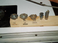
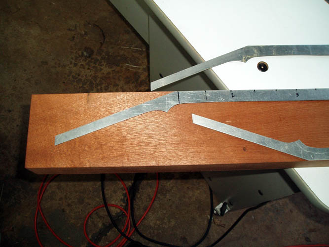
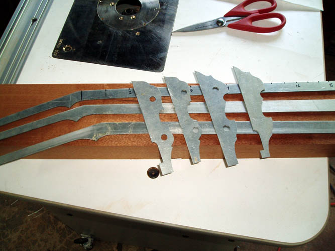
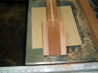
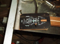
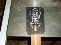
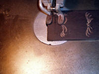
My aluminum neck templates were used to trace the side profile onto the
raw neck blanks and had three for varying thickness necks
required/requested. The peghead templates above includes two
that are needed for the Gibson style six banjo which had the gold sparkle
and black white peghead outline material. Those were cut entirely by
hand but today a good router fixture set-up would make it a lot easier and
probably more accurate but I did not have that many calls for the style six
binding but had it available for sale which most builders cut and fit it
themselves.
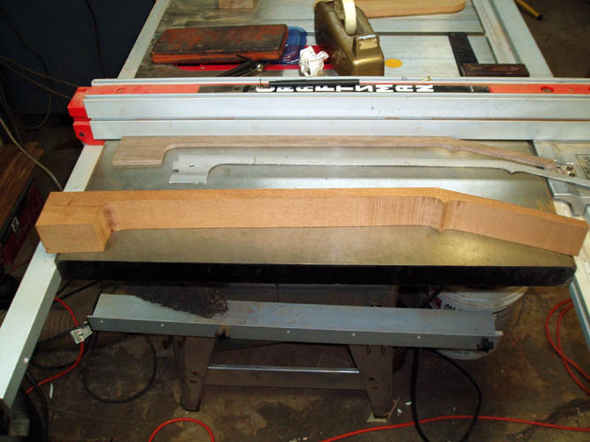
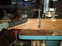
Before I can get much further with the neck, I have to remove the 1/2
inch width band saw blade and install a 1/4 inch wide blade to
accommodate the tight turns required for the neck but could do it with the
1/2 inch blade with a lot of chiseling type cuts but then we get into some
serious sanding and clean-up work. I had rather spend the extra set-up
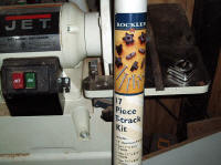
time for the band saw blade. I have a set of Carter ball bearing upper
and lower guides on the ole Jet 14 inch band saw which is about worn out but
should be accurate enough for the profile. I currently use the band
saw for resawing turkey box call lid raw materials only.
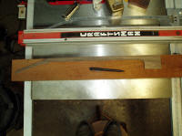
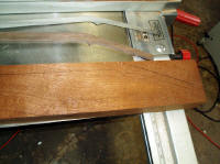
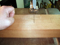
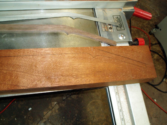
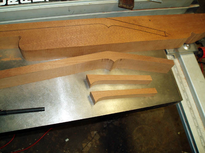
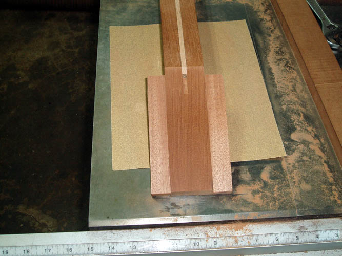
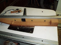
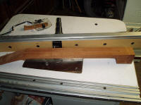
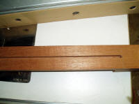
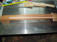
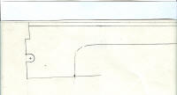
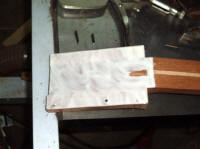
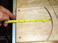
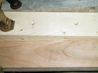
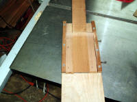
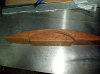
Neck side profile pattern traced onto Honduras Mahogany wood blank large
enough for two (2) necks and cut as close to the line as I could.
Since I will be shaping the neck contours with hand tools, the pattern I
traced will put the neck thickness taper from the nut to the 17th fret about
where I need it and will use a standard 3/16 inch thickness fingerboard.

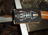
The peghead "ears" were cut out of the excess neck blank material and
didn't need the entire side profile cut but it has been decades since
building a neck and/or banjo so a little extra material want hurt any....if
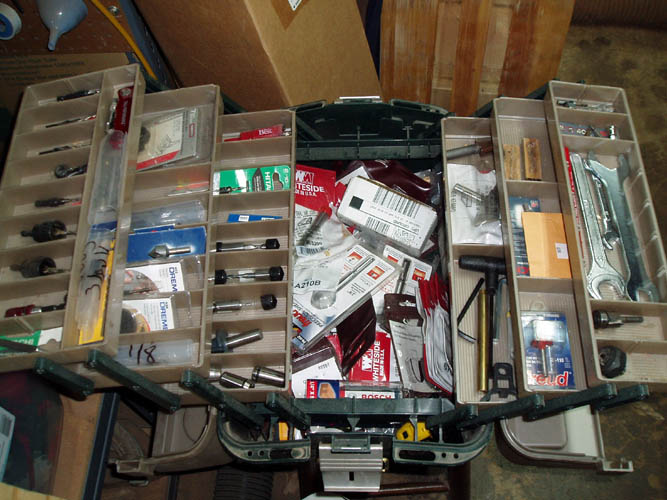
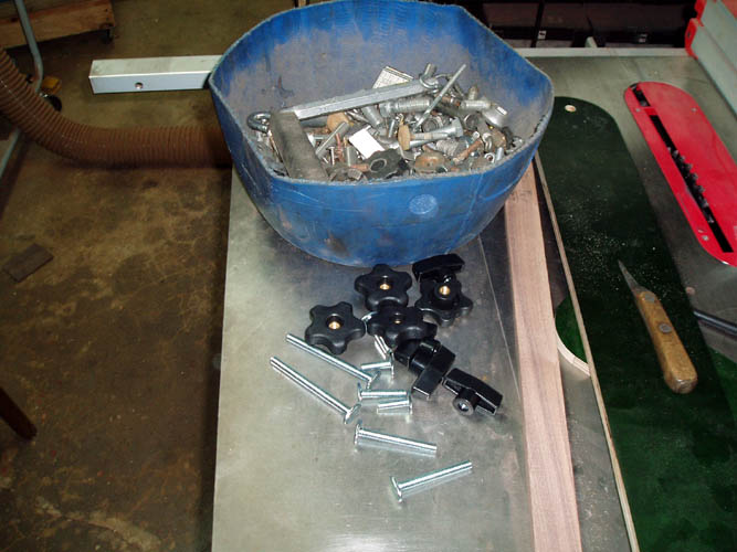
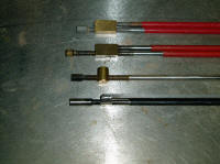
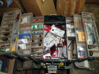
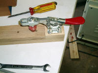
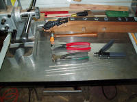
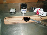
anything, will have more room to attach the clamps later. I have at
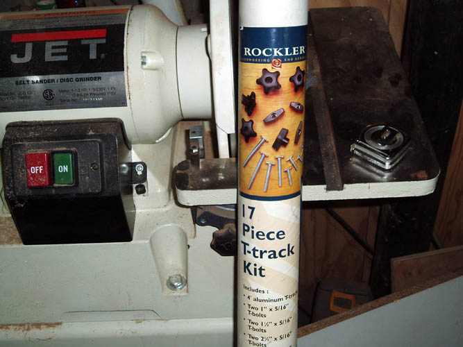
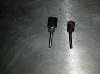
least five (5) different style two-way adjustable truss rods and took a pix
of four of them.....the one not in the pix has a horseshoe shaped retaining
lug that positions near the nut area but it required an extra slot on either
side of the truss rod main slot so eliminated that one to begin with.
I decided on the one made by
LMI which requires a 1/4 inch wide slot,
however I like a truss rod deep into the neck past the neck center of mass,
although you can mount the truss rod flush below the underside of the
fingerboard. I am still "Old School" and old
habits are hard to break. I do think the single truss rod with less
weight definitely has its advantages but that is just my opinion and two-way
action rod is definitely superior but still doesn't remove any neck
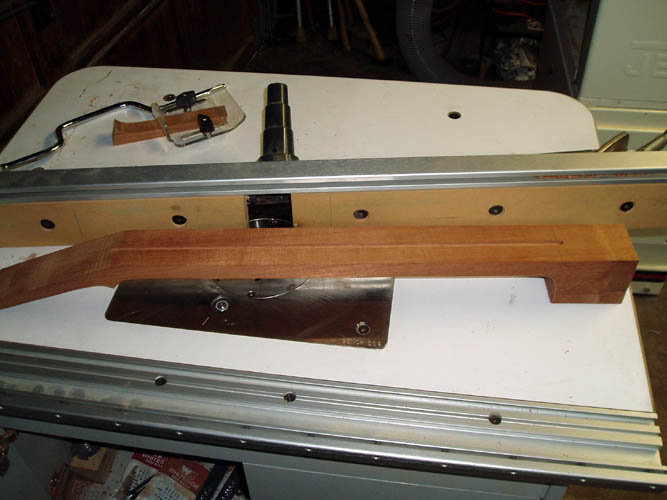
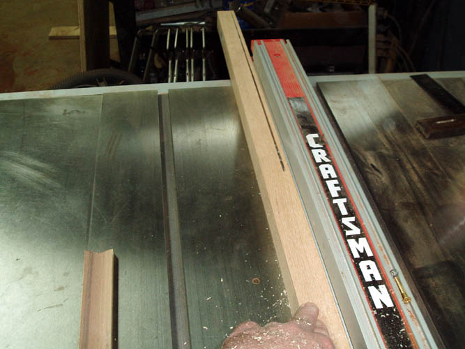
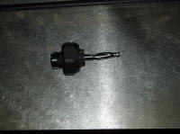
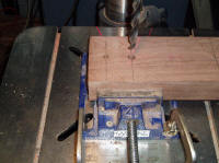
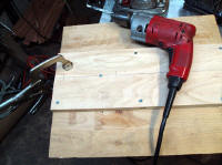
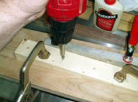
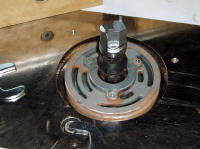
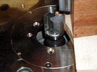
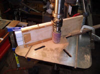
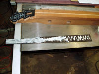
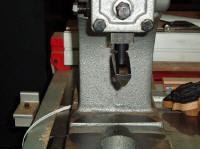
warp/twist! I decided to use the router table to cut the slot instead
of using the table saw and located a solid 1/4 inch diameter carbide two
fluted spiral bit from my turkey call router accessories box. My
router table is a Bench Dog and it has a ProLift which allows
you to easily adjust the depth of cut without a lot of hassle.
I have a Porter Cable Model 7518 3.25 HP router mounted to the
Pro-Lift router lift and the Porter Cable router has plenty of power but
one must remember a router is no substitute for a stationary shaper and the
router table has its limitations but you can
"milk" it and about 2 1/2 inch diameter cutters is the limit
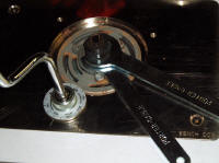
and great care must used and take multiple passes. The only
thing I don't like about the Porter Cable 7518 router, there is no
spindle lock and you have to use two wrenches instead of one when changing
router bits/cutters. Height adjustment is a breeze with the crank
assembly and the Pro-Lift is worth the extra expense.
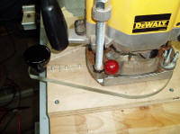
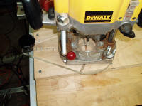
I modified the Bench Dog router table fence and use a simple bolt pivot
at one end instead of trying to get each end adjusted and even with the
original fence which had the means to allow for the double end adjustment,
it was a pain in the rear and still not accurate enough and too time
consuming. If you are needing a state of the art router table fence,
contact Pat Warner at
www.patwarner.com. The simple pivot works much better than the Bench Dog Pro Fence and I secure the free
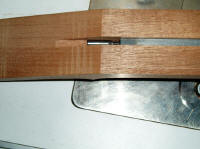
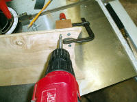
end of the fence with a C clamp to the table. I used a scrap piece of
material to get the fence set for the centerline of the neck slot and routed
to depth in three (3) passes instead of one. The router has plenty of
horsepower to cut the full depth in one pass but it is much safer and
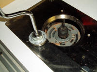
increases the life of your router bit as well. I stopped the cut at
the heel area instead of slotting the entire length of the neck blank.
What the heck, I have to be a little different from THE GREAT DEPRESSION
ERA Mastertones....grin if you must. I made a pencil mark on the side
of the neck blank and one in line with the router bit on the side of the
fence instead of affixing a stop to the fence and if doing multiple neck
blanks, definitely would have a stop in place
 .
.
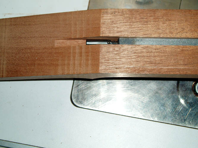
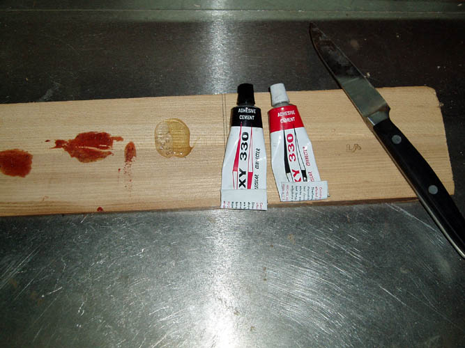
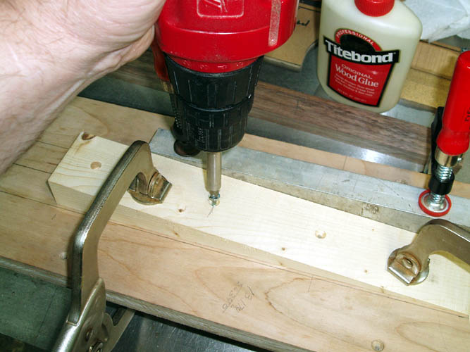
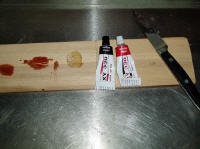
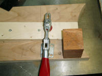
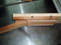
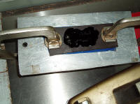
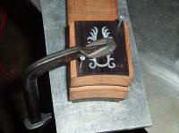
The LMI double action truss rod required grinding a bit of the weld area
at both ends to accommodate the 1/4 inch width slot and this rod uses an
Allen wrench which doesn't require routing or drilling to enlarge the access
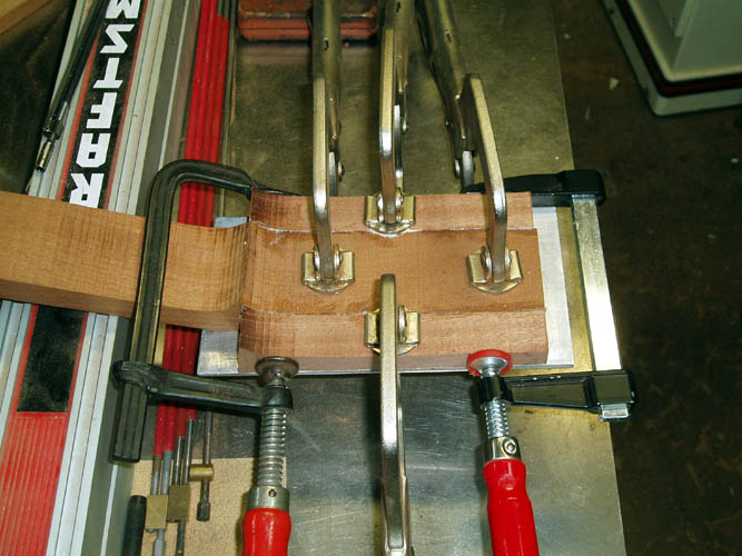
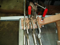
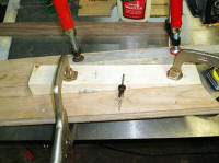
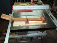
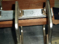
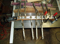
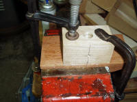
area. The peghead ears were glued in place using Franklin Original
Titebond glue and used a 3/16 inch thick aluminum plate as a support means.
I certainly don't have plenty of C clamps and a person needs at least a
dozen or two to do some serious clamping. I still have a couple of the
Bessie bar type clamps from the 1970s that are still functional. One
word of caution, don't ever attempt to make the wooden guitar adjustable
clamps without some serious jigs and fixtures....take my advise; buy them
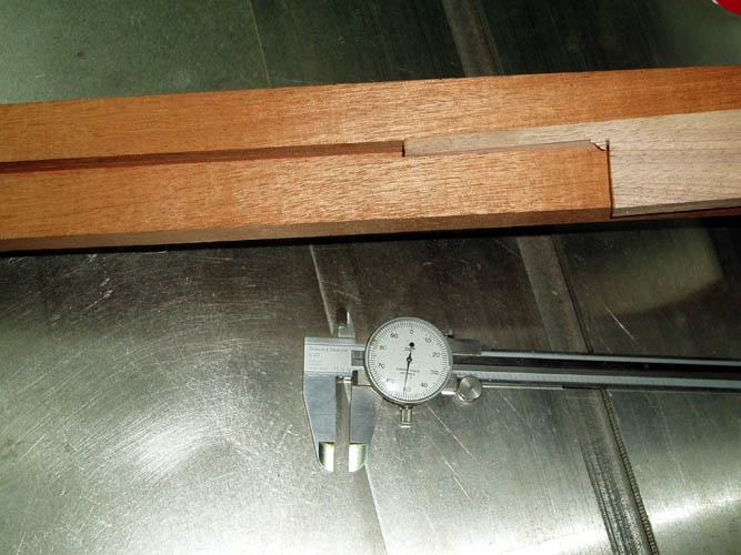
instead...Ok, add 2 plus 2 together! I plan to install a maple
filler strip on top of the truss rod and compress the rod together with
pressure from the filler strip to keep any would be rattle or vibration from
the truss rod. Since I don't have any maple in stock, will have to
round up a piece. I have some exotic woods in stock but want to keep
the weight down on the neck to a tolerable level.
Bill aka Mickey Porter 04-17-10.
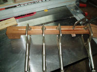
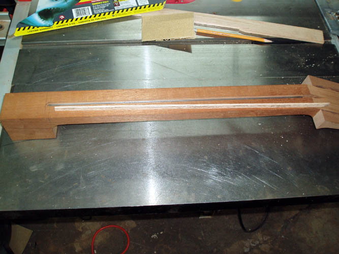
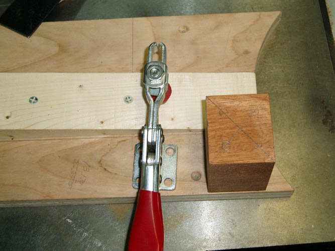
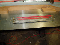
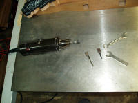
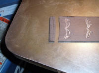
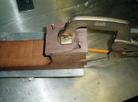
Above pixs of the two-way truss rod installation and placing a filler
strip on top of the truss rod. I used some scrap wood to cut a test
piece to fit the routed slot fairly snug but not so tight you have to drive
it in place. Whether or not such internal stresses inside the neck has
an effect on tone, timbre or volume, I can't say for sure but I do know you
want an instrument to be as stress free as possible in areas that can
produce vibrations and a neck certainly does do that. After a few test
cuts "tweaking" the fence setting on the table saw, I ripped a piece of red
oak which was between flat sawn and vertical grain orientation the proper
width and also approximate height required. I glued the filler strip
in place using Epoxy 330 and applied enough C clamps. Prior to gluing,
I scuffed the slot up a little with 100 grit sandpaper and also the flat top
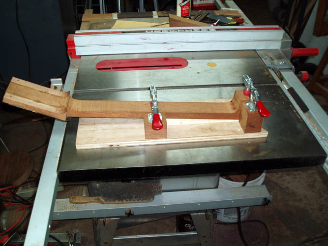
portion of the truss rod per the manufacturers recommendation. While
the epoxy cures out, I will band saw the neck profile of the remaining
portion of the Honduras Mahogany neck blank wood since I already have the
router set up. 04-19-10.

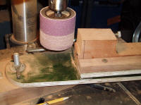
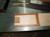
With a few turkey hunting outings under the belt, I sneaked in a few
hours to continue with the banjo project. I decided to make a
Rube Goldberg fixture to sand the 5.5 inch radius on the neck heel for the
two piece flange portion that contains the neck lag screws. I rounded
up what scrap parts and material I had on hand and quickly ran out of 1/4 x
20 tee nut metal inserts and had only enough for the hinge portion of the
fixture that will more or less control the neck angle. I will have to
drill and/or band saw the 3/8" tube portion and fit it by hand with a
gouge. The tension hoop portion of the heel, I am going to check my
router bits and see if I have something close to cut it and might make a
simple radius jig and use the router table for that. I don't know for
sure yet. I would have made an 11 inch diameter wheel on a bearing but
I no longer own a lathe and didn't want to route out a circle of which I
could have but trying to use what tools I have a hand and as easy as I can
too....grin if you must. A person that does necks on a regular basis
has no trouble shaping the radius portion of the neck heel after the profile
is band sawed to shape. You have to have your wood working skills
honed pretty good since this a very critical element. I have seen many
necks that had a right to left cant in the neck and the strings were not
centered from the bridge to the nut and favored one side of the fingerboard
more than the other. I used a couple C clamps to secure the neck
blank to the fixture for testing purposes and if doing more than one, I
would have fabricated something in tool steel with a bronze bearing/bushing;
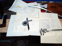
hopefully this little fixture will do! Again, without the benefit of
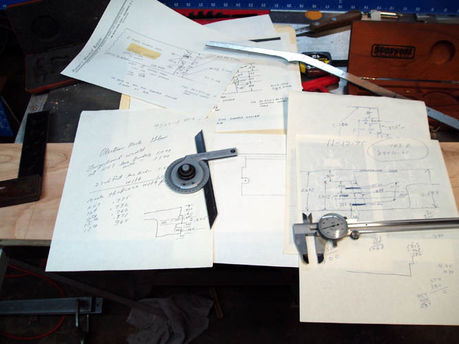
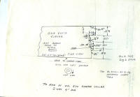
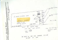
original necks to compare the heel shape/angle, etc. I dug through one
of my file cabinets and located some hand written notes about the time I had
special carbide tipped custom knives made for a Baxter Whitney double
spindle shaper cutter head of which the notes were taken from a Gibson
Plectrum Hearts and Flowers neck Serial Number 9220-2 and a couple TB3 early
tenor necks, Serial Number 8440-21 and the other one I didn't find a serial
number written down; all for the tube and plate flange. The
drawings revealed 87.5 degrees for the portion of the heel that contacted
the wood rim and 86 degrees for the stretcher band aka tension hoop. I
know this is a "ball park" neck set angle due to
the desired action and also the height of the bridge used and believe 3
degrees would be pretty close to the maximum neck angle for a 5/8 inch
height bridge with zero distortion to the wood rim circumstance. I
still believe that the adjustment of the coordinator rods per the original
pre-war instructions has damaged many excellent instruments over the years
by making the wood rim out of round and exerting unequal pressure on the
lower portion of the tone ring lip area. I guess the beauty part
of the tube and plate wood rim fit is the upper and lower portion that makes
contact with the neck with both being about 11 inches in outside diameter. I could
barely read the small markings on the Starrett protractor model C359
angle gauge and made a one to one scale drawing from the notes to cut the
side profile of the neck blank out with. Prior to the cutter head for
the shaper in the mid 1970s, I used dedicated single custom cutters with a
lower bearing utilizing a heavy duty drill press running about 6K rpms and
with a "stout" metal radius fixture, it cut mahogany and walnut like
warm butter and cut maple without burning it too. I am enjoying this
project for sure!
04-28-10.
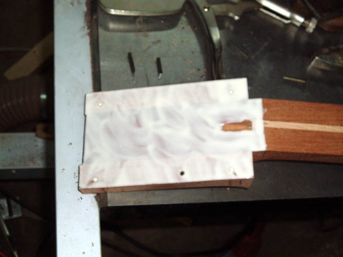
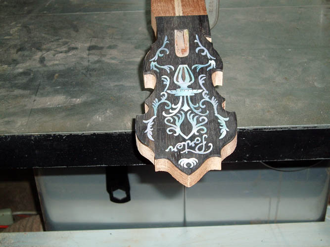
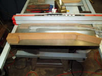
After allowing the neck to cure a good long time, I sanded the peghead down
using "Old World Techniques"; i.e., sanding and truing up by
hand...grin if you must! I certainly use my table saw table for many
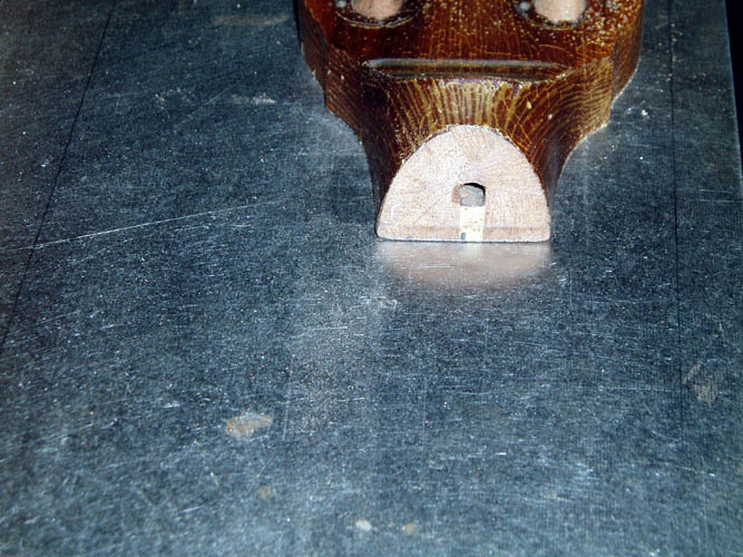
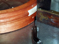
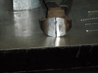
things other than cutting wood. Next pix or two, I cut the neck notch
out removing the radius portion of the wood rim for the tube of a tube and
plate wood rim that I purchased from Jimmy Cox several months back and had
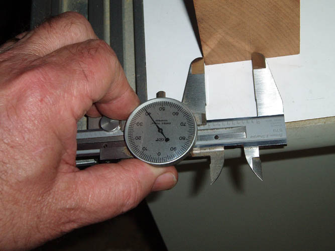
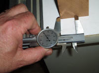
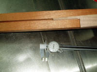
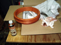
some stain on it and letting it age also. I noticed on this wood
rim that the lower portion below the plate area which is normally 11
inches in outside diameter was about .018 inches under size which equates to
a total outside diameter of 10.964. I checked the gap with a feeler
gauge and it want make much difference except the neck heel will have to
accommodate the difference since the lower wood rim portion and the tone
ring will be .018 inches from true parallel and the neck fit will have to be
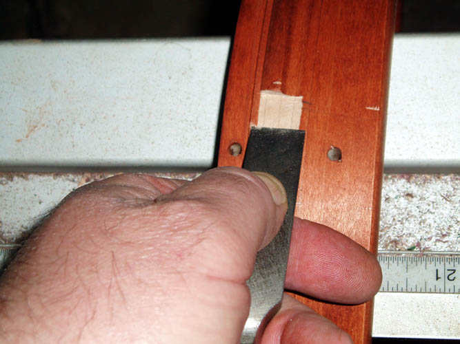
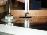
"tweaked" for a perfect fit. No big issue. The pix
of the wood chisel is certainly not the way to make this cut but had to
"stage" it for the photo...grin if you must....when using any type chisel,
it is best to have two hands on it and use it like a fulcrum to prevent
slippage which can ruin a part. Also, I have a 6 x 48 inch belt
sander, and 12 inch diameter disc but they are more aggressive than I care
for and didn't mind the hand sanding part at all. One could use a
small router and guide to cut the neck notch portion out of the wood rim but
you still have to square up the corners that the router bit leaves so again,
"six of one and half a dozen of another". Ascertaining the wood grain
direction is important when removing wood with hand tools. I will
final sand the wood rim and apply another coat of stain before starting the
finish.
05-01-10
PS Turkey hunted this morning until around 10sh
but didn't hear or see a turkey but enjoyed the owls, crows, hawks and other
things that kept me entertained!

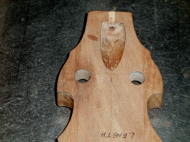
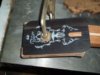
 Gibson pre-war TB4 cannibalized peghead for the overlay.
Above pixs of a
TB4 peghead I received from C.E. Ward decades ago that he cannibalized to
convert to an RB4. This shows a behind the scene of what a Gibson
production environment looked like back in THE GREAT DEPRESSION ERA .
The peghead and fingerboard were way off center of the neck blank and the
center line of the cut out for access to the truss rod is off line as well.
The craftsman that did the above work must have been on the NC Blue Cross
and Blue Shield Insurance "Eye Plan"...grin if you must!.
Those Great Depression Era
Gibson Craftsmen sure know how
to make it happen! I collected most of the stuff C.E. Ward
cannibalized, however about all of it is since long gone. C.E. could certainly
make a new neck look pre-war!
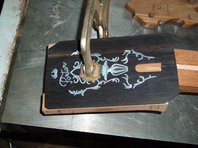
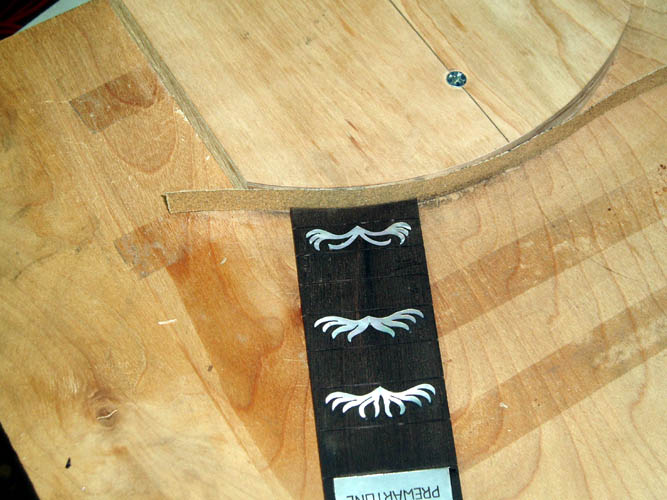
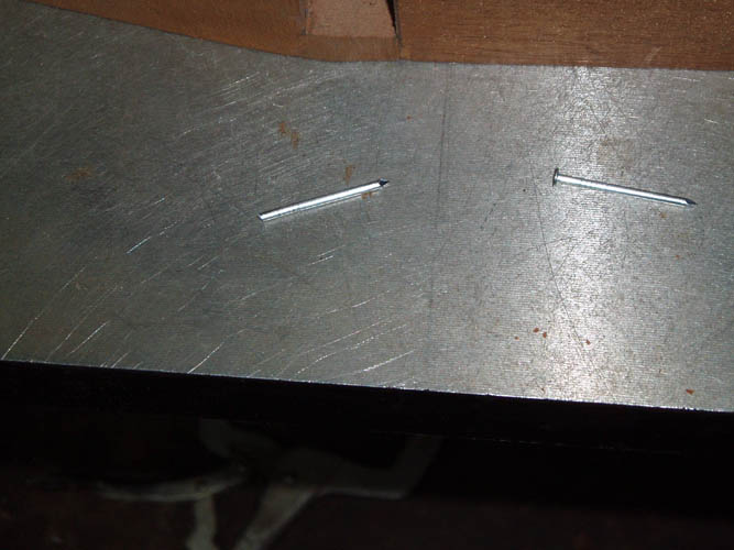
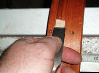
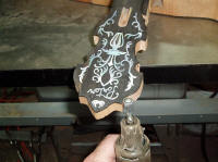
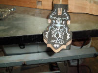
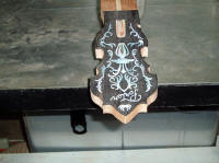
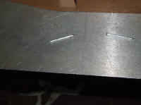
Had a chance to "mess" with the banjo neck a little this morning and glued
the peghead overlay to the neck blank. The above pixs shows using a
.159 diameter common nail that was cut off to the required length and used
to "pin" or located the peghead overlay position to the neck blank peghead.
Without some type of pin or alignment system, it is a sure bet the overlay
will slide or move around if you are not careful or real lucky! I
planned on using a galvanized roofing nail which was slightly under .125
inches but mistakenly used a 9/64 inch diameter drill and had to regroup and
use a larger nail. A set of number and letter drill bits certainly
does come in handy for mistakes such as this one......grin if you must!
There is no use to buy pins for this purpose from musical supply houses
unless you enjoy adding income to their retirement portfolio package.
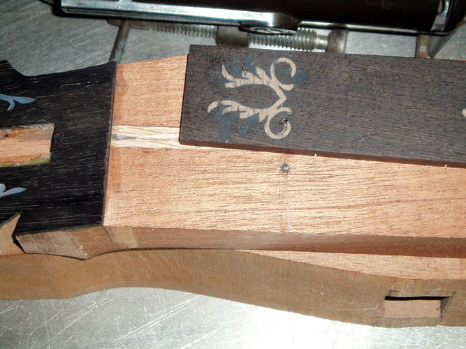
First, the peghead was positioned in the proper place and witness marks made
with a pencil to align the two and C clamped into place and drilled the
proper size holes in an area of the peghead that is scrap material.
The nails were cut off and ground one end flush which isn't really
necessary. Franklin Titebond Original glue was applied to the neck
blank peghead and you could let it set a few minutes if you wanted to but
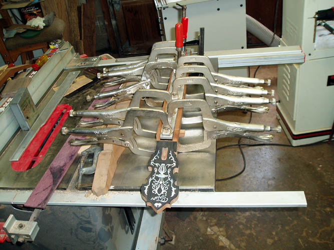
with the usage of the nails aka pins, it is not necessary. I used a
3/16 inch thick aluminum backer plate and enough C clamps to ensure the
peghead overlay will have equal pressure applied to ensure a good glue line.
In a production environment, it would be just as easy to reference the tuner
peghead holes to the peghead overlay if your jig and/or fixture is accurate
enough but the above works for a small shop or just one neck.
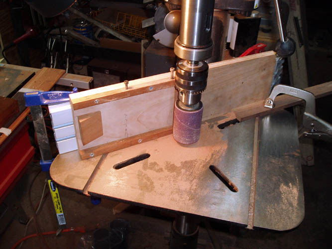
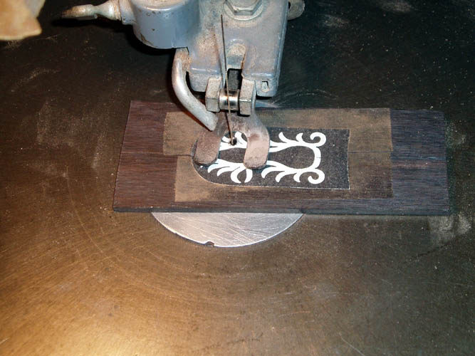
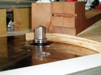
The third
pix from the left
above shows a table router set-up where I routed a 3/16 inch wide groove for
the nut on a piece of scrap material. I plan to route the end of the
peghead and recess the 3/16 inch width nut about 1/16 to 3/32 of an inch
deep into the neck blank depending on how much nut blank height I have to
work with. Most of all THE GREAT DEPRESSION ERA Gibson banjos
recessed the nut because they used a 1/28 inch veneer overlay for the
headstock and that does not offer additional support for the nut.
Makers today can get away without recessing the nut into the neck because of
the usage of 1/16 to 3/32 inch thick peghead overlay which gives enough
support to the lateral string tension applied to the nut blank. Glues
today are also strong enough to do more than an adequate job as well.
You can grind/sand the angle of the peghead overlay that abuts the nut or
use a small stiff back fret saw to do the same thing. I will test run
a piece of scrap ebony to see how much tear out is present but there is
plenty of excess material since the peghead is still in the rectangular
shape. The pix on the right above is the router set-up I used to cut
the extra length (overhang) of the peghead overlay off at a right angle to
the fingerboard. I checked the nut blank height and don't have enough
extra material to route a slot much depth at all into the neck for the nut
blank. I used a small bar clamp to hold the neck blank and the lower
wood spacer tight against the miter gauge into the router table T slot and
pushed the material into the router bit and there was minimal tear out of
the ebony peghead wood overlay. Next on the sequence will be the
pre-shaping of the heel to fit the wood rim or I might apply some finish to
the Jimmy Cox wood rim first.


I wasn't satisfied with the notch cut-out on the wood rim and decided to use
my router table with a flush cutting router bit and guide bearing below and
flush with the two fluted solid carbide tipped bit to ride against the lower
portion of the wood rim and get the wood rim cut-out a little closer to
parallel with the upper portion above the tube and flush with the tone ring
which is the ideal configuration. There was about 1/4 inch at each end
of the cut-out that required a small sanding block to finish the cut since
the router bit had to stop short due to the 1/4 inch radius. The
adjustable router fence was position against the wood rim to aid in
steadying the wood rim but this is certainly not a fail safe
recipe and you could ruin the part or "bugger" it up with a
slip. I would not recommend this cut unless you are comfortable
with your router and table set-up. A more fail safe approach would be
to make a 5.5 inch radius guide to keep the wood rim contained in with a
notch for the router bit and securely anchored to the router table. I
did a trial fit of the tone ring which was easy to remove a month or so ago
but noticed I could hardly get the tone ring off the wood rim and decided to
see what had changed. After a close inspection, I noticed that the
center lamination had apparently turned loose from the 3rd ply for several
inches with the center lamination slightly below the 3rd ply which is not a
good thing since it was flush when I purchased it. I could press the
3rd lamination inward and see and feel the gap closing up. This opening up
of the lamination increased the outside diameter of the wood rim portion
that contacts the "lip" area of the tone ring and accounts for the tighter,
although I don't think it will be a serious problem at this point unless it
opens up further. This is a problem
that has plagued rim makers including Gibson for many decades and sometimes
doesn't show up until years down the road. I will monitor the glue
joint and if necessary, apply some thin glue into the crack and pull it
tight before the finish is applied. I opened up the holes for the
neck lag screws since they were several thousands undersized and drilled
them to 3/16 inch diameter which is right for the neck lag screws I will be
using. I could have forgone removing the outer radius of the wood rim
and simply made the neck heel cutout to fit around that segment which some
current builders are doing to save some labor. However, I am still
old school and whether real or imagined, I like the concept of
having as much neck heel making contact with the wood rim and tone ring as
possible. Some banjo owners/technicians try and isolate the contact
between the heel and the tone ring thinking the tone ring actually vibrates
and moves like a guitar top but I don't see it happening....each to his/her
own theory. I am a "Doubting Thomas" on that procedure.
There are many theories about this and the heel to tone ring fit was good enough
for The Depression Era Mastertones although I am sure the method of rim
construction with the tongue and mortise for the fourth (4th)
lamination played an important role in the neck heel configuration as well.
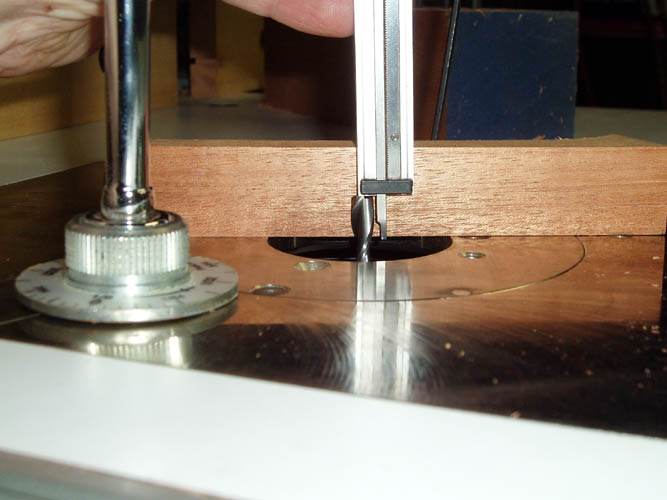
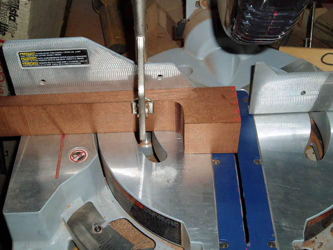
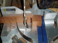
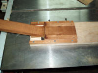
I did a few test run cuts with the miter saw to get the table
angle set to 87 degrees and got it set close enough for "Government
Work", no pun intended....grin if you must! One
could just as easily band saw the side profile since it will be finally
shaped to the 5.5 inch radius to match the outside diameter of the wood
rim...again, "six of one and half dozen of another."
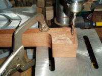


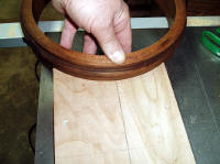

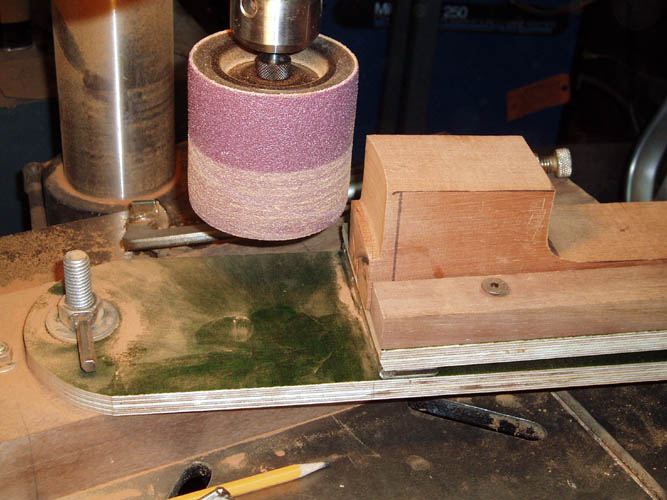
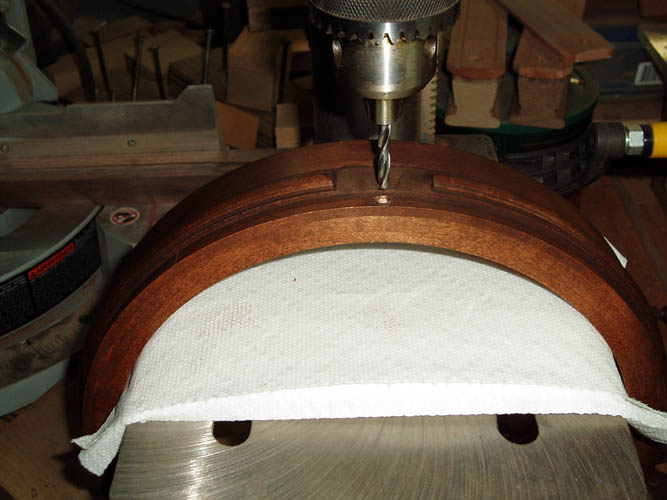
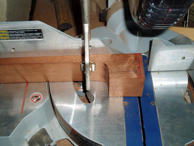
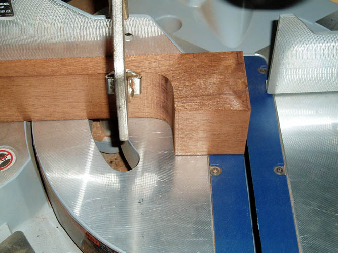
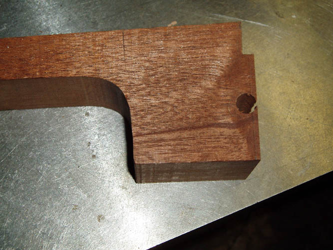
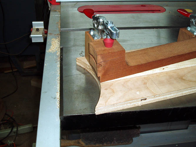
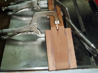
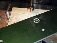
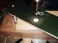
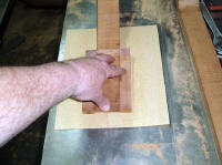
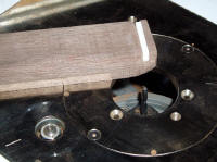
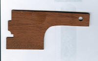
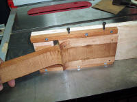
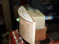
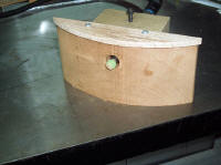
Above segment of pixs shaping the neck heel profile. After the pattern
was laid out on the wood, I drilled a 3/8 inch diameter hole about .200
inches inside the heel....this gives a little room to work with since the
actual tube diameter is .375 inches less the flat portion removed for the
plate to rest flat against and the overall width will be .400
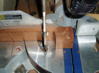
inches east to west. The miter saw was set at 87 degrees and the cut
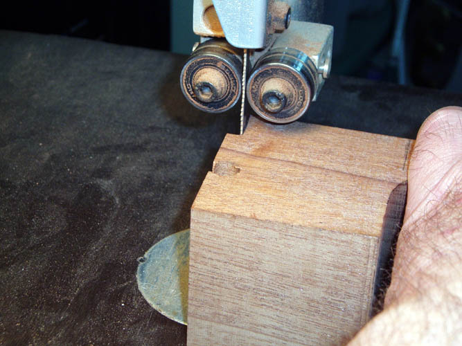
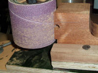
made. Next, the tension hoop portion was band sawn to the side
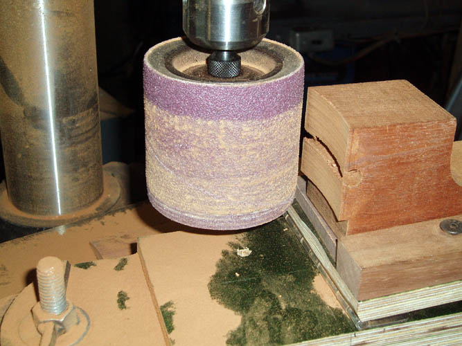
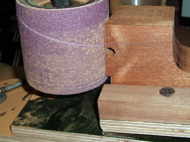
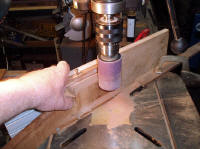
profile. The 3"x3" sanding drum in the drill press and radius fixture were
used to sand the 5.5 inch radius to the straight 87 degree cut made to match
the wood rim outside diameter. The tube portion curvature (5.5"
radius) will be cut with a gouge or the Dremel tool. For the radius
portion of the tension hoop area, I constructed a very simple radius fixture
to use on my router table and will use a flush cut lower bearing pattern bit
and elevate the heel to 86 degrees and route radius portion. The angle will be
off on the bottom of the cut since it is normally parallel to the
fingerboard and will fix that with the Dremel tool. The fixture was
screwed down to substrate 3/4 inch thick plywood with countersunk flathead
wood screws to keep the part from
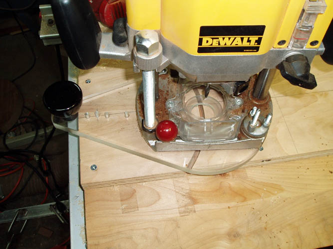
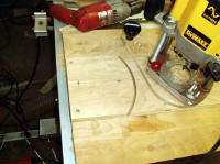
moving once the router bit cut through the radius pattern. I used a
heavy duty DeWalt model 625 3HP plunge router and a solid two fluted spiral
carbide bit and made several passes to cut the fixture radius to depth. The
off-set router base
manufactured by Pat Warner at
www.patwarner.com was drilled with a 3/16 inch diameter drill bit at
exactly 5.5 inches away from the leading edge of the router bit and a 3/16
inch diameter hole was drilled into the fixture and a 3/16 inch diameter pin
was inserted into the hole and the off-set router base was inserted onto the
pin to allow the router to rotate in a 5.5 inch radius. After the router cut was made, I
removed the retaining screws and will affix guide centering rails to
properly align the center axis of the neck to the radius. While I was
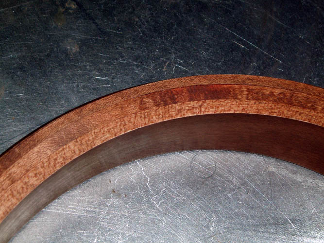
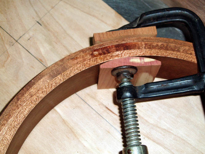
checking the Cox wood rim, I decided to force some Titebond glue into the
crack between the center and outer lamination and pulled it closed with a
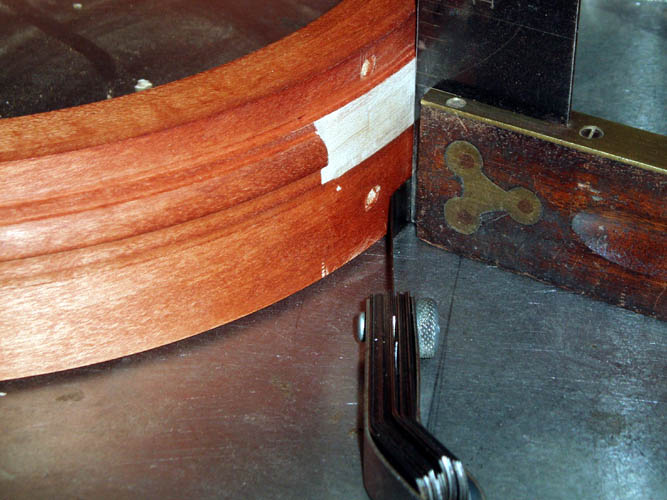
Bessie clamp and a couple curved "cauls" to keep from marring the wood rim.
Observant viewers will notice two different stained colored rims; I
didn't like the light color of the maple and went back over it with some
brown walnut stain. The maple looks more to The Great Depression Era
but I have seen all shades in between and beyond too!
I know
what you are thinking; this is a lot of fixtures for only one neck but
I might want to do another one....grin if you must and I already have the
scrap material on hand to do it with and enjoying the laid back approach to
this banjo.....a far cry
from my former banjo making days with good accurate tooling and
fixtures! A good spindle shaper and profile blades in a cutter head would be
the ticket for this one but using what I have "at hand."
Back to the completion of the neck radius fixture for the tension hoop and
fingerboard portion:

To cut, shape and/or route the tension hoop/fingerboard of the neck blanks
if not using a shaper with dedicated cutters and fixtures or an 11 inch
diameter by 1 inch thick cylinder with sanding paper affixed to it which
also requires a dedicated fixture to move the end of the neck heel slowly
into the spinning cylinder with the right to left axis correct and the pitch
correct as well, therefore I elected not to cut it by hand using wood
chisels, Dremel tool etc. and not having easy access to a lathe, the above
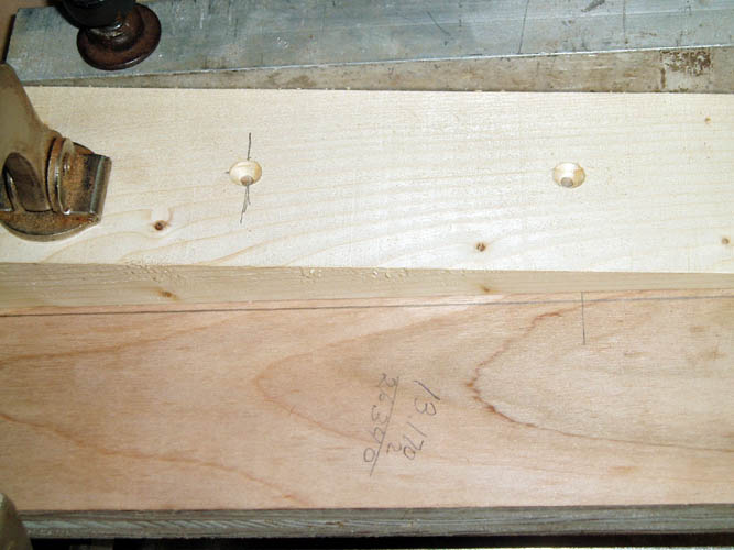
fixture came to mind. In the above pixs, I cut a four (4) degree
taper/wedge from a scrap 2/4 stud using the band saw and screwed it to the
base plywood which contained the 5.5 inch radius to match the wood rim aka
pot assembly. I drilled and countersunk three screws using a 1/8 inch
diameter tapered drill bit with countersink attached and the cheap ones you
buy from Lowe's, etc. are a waste of your money. I special ordered
those from a drill bit company in PA and can't remember the name of the
company right off the top of my head. I had a large DeStaCo # 235U
clamp but it was way too large for this fixture and needed a couple DeStaCo
225U horizontal clamps although the vertical handle orientated toggle clamps
by DeStaCo would work just as well. I use the saying "Rob Peter to Pay
Paul at work when it comes to materials and supplies in this tight economy
and that is exactly what I had to do since I wanted to get the fixture made
since I had some free time to do so. I removed a couple clamps from
one of my turkey box call jigs and cut the proper height mounting blocks and
screwed them to the fixture using flathead wood screws and countersunk them
from the bottom of the fixture. I made one mistake since the 1/8 inch
diameter for the pilot hole was too small and the lower portion of one of
the blocks split open and had to go back and drill larger diameter holes
.149 for the correct fit. The cheap Taiwan wood screws I had that were
the proper length, a couple of them broke off but was able to salvage the
mahogany wood block with some Titebond glue. That piece of Mahogany
was very hard and brittle and softer wood would have been fine with the
tapered drill hole. After going through my router tool box, I couldn't
find a pattern bit with the bearing on the bottom for use in my table router
and had to order one. What I have on hand was too long and this
application required between 5/8 inch to 1 inch in length....you have some
adjustment with the 3/4 inch thick base of the jig to position a one inch
router bit to the proper length. I had a template bit the correct
length but it has the bearing above the cutters for usage with a regular
hand held router and not suitable for this application. When the pattern router bit arrives, I will give the
fixture a test run. Also, with using any dedicated fixture or jig
which normally means you will be doing multiple items, your parts have to be
sized pretty close to keep from having to readjust your clamp pressure.
The neoprene tipped hold down bolts gives you about 1/8 of an inch to play
which allows maximum clamp pressure of 500 lbs. which is very liberal
indeed. This fixture will also allow you to place a thin piece of
sacrificial wood next to the heel where the cutter will
exit if you feel there is a tear out problem. If you have pre-cut your
side profile out pretty close to the final shape, there will not be much
material to be removed at the edge of the heel but will simply be flush with
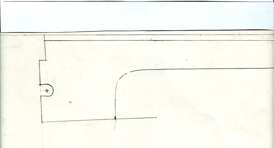
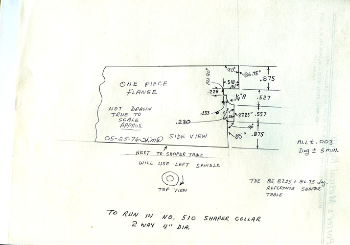
the lower 5.5 inch radius pattern. I will add a couple scans of the
one piece and two piece flange heel shapes with measurements taken off
cutters I had made in 1976. I believe John Bowles of Advance, NC still
has those cutters that fit into a 4 inch diameter cutter head for an old
Baxter Whiney double spindle shaper.
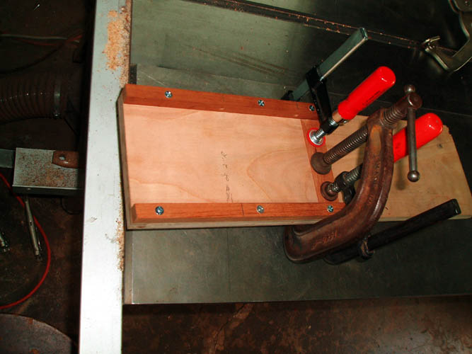
Above pixs of the router table set-up using a standard 1 1/8 inch diameter
pattern with cutter length of 1 inch and positioned where 5/8 inch length
will be doing the cutting about and flush with the radius pattern guide.
The above fixture gives the proper radius and also the 4 degree angle
required from the fingerboard but will still need to made the lower edge of
the area below the lip on the banjo head parallel with the fingerboard plane
instead of being offset which a little hand work will get that done since
the major radius and angles are in place. I know this might be doing
it the hard way but I don't want to make any major mistake on this critical
area of the neck. There was not any tear out on the router exit end of
the neck heel since it was abutting the clamp block which was by design.
Again, a dedicated cutter and fixture is the way to go for a production or
small shop operation!
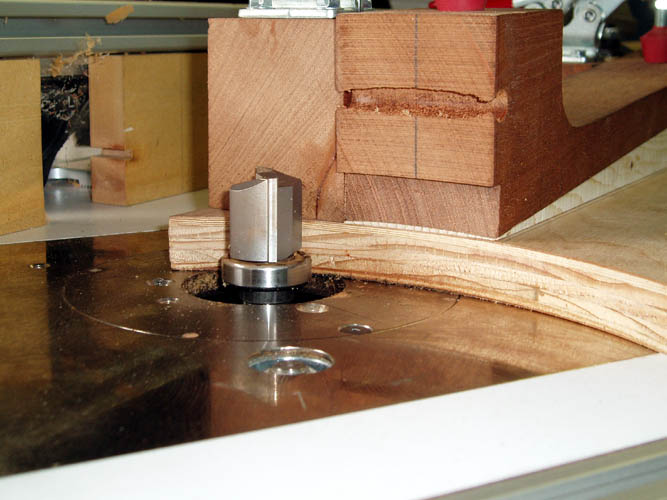
I have stated earlier that the one piece flange heel had as many as five (5)
different sizes since its introduction due to Gibson beefing up the die cast
one piece flange for strength purposes with each revision of the die.
The above drawing more or less fit the standard one piece die cast flange
that was available in the early to mid 1970s. I had an earlier cutter
made for the first Gibson production run of the one piece flange banjos,
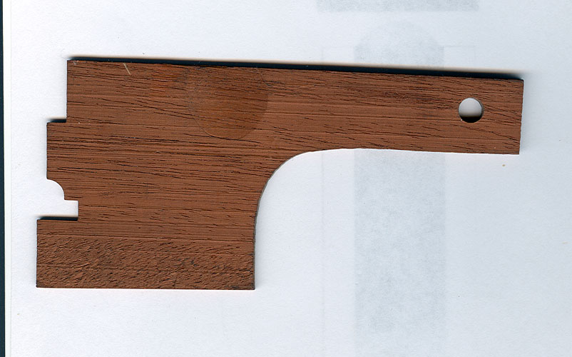
circa. 1929, etc., one piece flange. Pix on the right is a cut from an
actual neck blank that used the one piece cutter I had made for the post war
one piece flange that still worked fine for the pre-war one piece flanges
since it was oversize in the area of the flange fitting. . The above cutters had extra
length to the top and bottom cut whereby you could adjust the height of the
shaper spindle to include cutting the fingerboard at the same time but a
little risky due to tear or chip out on the exit side of the neck blank.
I supplied a pile of neck blanks in various stages of completion back in the
1970's via mail order and local pickup as well. Those cutters
would most of the time, get you right on the mark without having to do any
"hand work" of the heel, but there were many exceptions to the rule since I
have seen original Gibson pre-war banjos with all sorts of non-standard cuts
on the wood rim and heel configurations. Also, the heel angles vary
due to the different thicknesses of the lower portion of the wood rim even
with a standard one or two piece flange set-up. Gibson was a highly
production orientated company back in the late 20s and during THE GREAT
DEPRESSION ERA and not every Mastertone banjo they produced was a
"Holy Grail" specimen contrary to what many want to believe! Nonetheless,
they are today's Benchmark for a bluegrass banjo.
My next area on the neck will be the sanding down the back of the peghead to
the proper thickness with the 3/32 inch peghead overlay installed. On
most of THE GREAT DEPRESSION ERA Mastertones there is at least a .062 to
.075 inch taper of the peghead thickness from the 2nd and 3rd tuners to the 1st
and 4th tuners and have seen the thickness vary as much as 1/32 inch from
banjo to banjo. Many use a dedicated fixture to shape the back of the
peghead with cutters which can be dangerous and sometimes presents a tear
out problem but the much fail safer method for a small
shop without the benefit of a carving machine, CNC routers or spindle
shapers, is to use a sanding system; either by hand/eye or with a
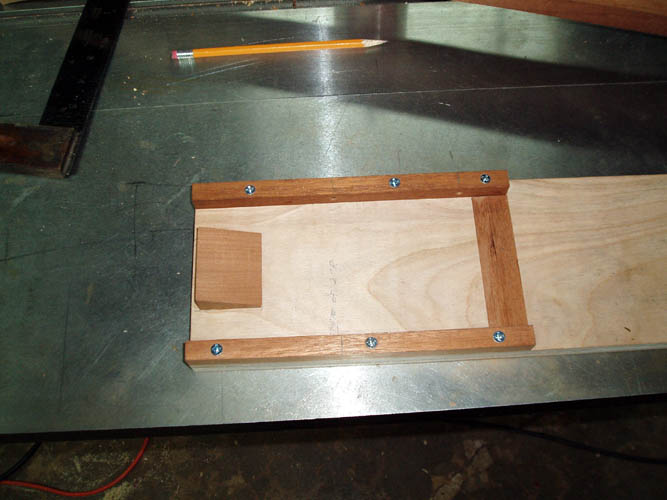
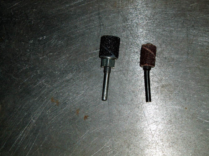
simple fixture and sanding drum, etc. I fabricated a very
simple fixture to use with a standard 3 inch length x 2 inch diameter
sanding drum which is not long enough but you can make two or more passes with it on
a drill press. A heavy duty oscillating spindle sander will do
this area and also the standard fiddle and double cut peghead shape with
ease since many of them have an assortment of spindles/drums ranging from
1/4 inch in diameter all the way up to 3 inches in diameter and most are at
least 4.5 inches in length with about a 1 inch stroke. I did a bunch
of pegheads with nothing more than rat tail files and small sanding drums
with a Dremel model 280 tool but the oscillating spindle sander does a much
quicker job and with more precision due to its vertical orientation and
longer spindle travel.

The above fixture was construction out of 3/4 inch thick Birch plywood with a
few strips of scrap Honduras Mahogany screwed into place to allow the
peghead to be firmly positioned onto the fixture/slide. The upper
strip of Mahogany has two 10-32 tapped holes for a couple socket head
Allen screws to apply pressure between the top middle edge of the peghead against
the lower strip which will hold the peghead in place as it will be moved
against a vertical edge guide into a 2 inch diameter sanding drum.
Where the tip of the peghead area starts, I have an elevation tapered wedge
that is around .070 inches thick glued in place and will provide a taper
from the tip of the peghead to the rear where the start of the radius for
the back of the hand volute. A 4.5 inch length sanding drum would be
the ideal for this and would require only one pass to sand the peghead to
thickness. I did quite a few necks with an ole Rockwell 6
x 48 inch length belt sanding station with the top dust cover removed and just
eye balled the back of the peghead against the sanding belt but a fixture works much better!
After the fixture was constructed, I clamped a piece of extruded aluminum
channel onto the drill press table and set it a little over 9/16 of an inch
from the sanding drum to do a test run and see if I was in the ball park.
I clamped a strip of wood against the sliding fixture at the far end
of the fixture to help keep it against the base of the aluminum fence and
used this as a reference to move the fence into the sanding drum for the
thickness adjustment of the back of the peghead. If you plan to do replacement
Granada
or #
5 Deluxe 5-string necks, you need a system that will allow you to
have as near a perfect flat surface on the back of the peghead to properly glue a veneer onto the back of the peghead with precision and a peghead
sanding fixture such as the above will get the job done. I would
recommend a much harder wood for the top portion of the fixture for the
tapped screw holes since the Mahogany will not hold up after much usage.
For continued usage, a metal threaded screw insert would be superior.....I
didn't haven any on hand so used what I had without them. Purple Heart or Cocobolo would be my choice
for the top strip to contain a threaded insert of just tap the threads
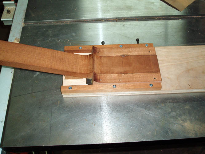
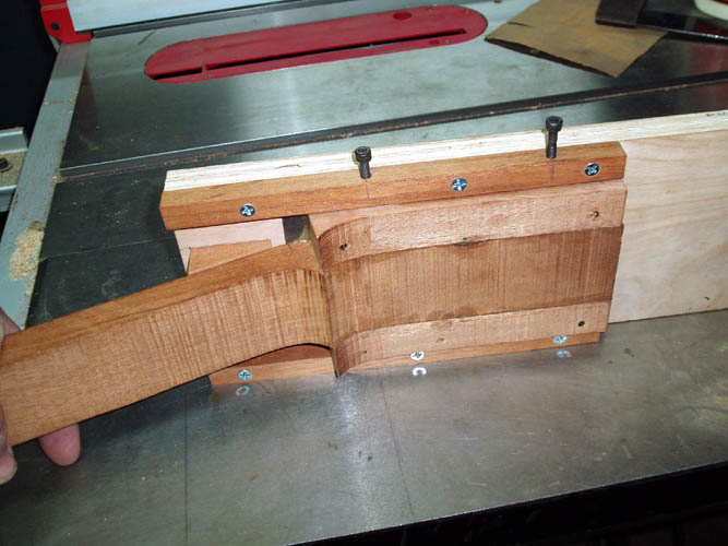
directly into the wood! On
the fourth pix on the upper right above, you can see the taper of the peghead in
the fixture but less than 3/32 inch will be removed from the back of the
peghead since it was band sawn to allow for the 3/32 inch thick peghead plus
a little overage for sanding to final thickness. The fixture slides
parallel to the sanding drum but the fixture has the built in taper needed.
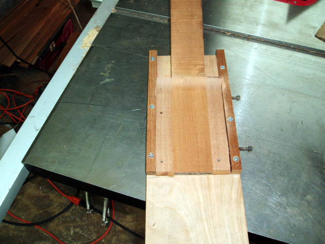
Inserted above a few
pixs of the sanding drum and edge guide on the drill press in usage.
If you want to spend some extra time and expense, a drawer type carriage
system would work just as well to move the peghead into the sanding drum.
I made several thickness adjustments to the fixture fence setting and took off about 1/32
inch and only sanded about 1/4th of the height instead of trying to do it in
a couple of passes simply because I had a case of mild dyslexia concerning
the rotation of the drill and should have feed the material from the right
side of the drill press into the sanding drum and didn't want to flip the
fixture over and drill and tap two more holes for the Allen screws....grin
if you must! Therefore, I was feeding the material with the rotation
of the sanding drum instead of against it which is the same thing as a
climbing cut with a router which is not the best way to do it.
The final fence adjustment rendered a peghead thickness around .530 at the tip end and .610
inches at the start of the radius of the volute which will be a little less
when finish sanded. I changed sanding drums to a 150 grit versus the
50 grit and got a better finish. It should not be a problem to
finish sand with a sanding block, or palm sanders.
I will probably rough band saw the double cut peghead next and get ready for
the installation of the inlaid fingerboard. I am still "Old
School" and plan to install the frets flush with the edge of the
fingerboard instead of over hanging the frets on top of the binding. I
don't think .030 to .040 makes that much difference as to the additional
fingerboard area gained and if you are not very careful with the fret
installation job, it is very easy for the 5th and 1st string to hang
underneath the over hanging fret. Grinding binding or grinding frets,
still labor either way you go. I will agree that the over hanging
frets might have more "eye appeal" than flush with the fret board
but that is a matter of opinion! I
suspect that many of the ole Great Depression Era Mastertones had the
fingerboard frets glued in with hide glue prior to gluing the inlaid
fingerboard onto the neck blank and I believe that George Hall commented on
that as well but memory has faded and not certain. Gibson has done it
several ways over the years.
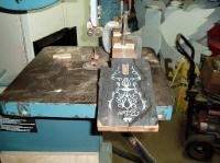

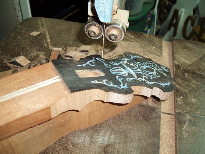
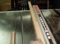
Above pixs band sawing the double cut peghead profile to rough shape.
I located the wood block that I used back in the 1970s to hold the neck
fingerboard parallel to the saw table and the neck is held in place with a
couple small C clamps. I used a couple small parallel machinists
clamps back then instead of the small C clamps as shown above. I traced the double cut peghead outline onto
the ebony peghead overlay and a regular white pencil didn't show up very
well and a regular lead pencil was easy to see with the light fixture
positioned at the right angle to the work piece. The double cut
template was only 1/2 of the actual peghead assuring a good matching
pattern, however the current templates made from clear Plexiglas works great
and those produced by CNC routers are near perfect. The smaller table
on this 14 inch Jet band saw is small for the old holding fixture since my
band saw in the 1970s was a 20 inch one and the larger table was excellent
for this type of sawing. With the double cut peghead shape you can cut
close to the outline on the less acute curves, however with the smaller
radius turns you have to use a chiseling method sawing parallel lines, a saw
blade width apart and then continue this until you have the pattern cut
close to your line. If you band saw blade has much kerf in it, you can
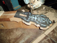
cut from the side of the blade as well. I stayed slightly outside the pencil mark and got
very close to the line which was surprising since I rarely use my band saw
"freehand" and didn't "bugger" it up any.
There are more refined methods to trace the peghead outline such as scribing
around your template and applying white powder or paint into the scribed
line. I will try and locate a 1/2 inch diameter small drum sander for
the Dremel tool and I still have plenty of 1/4, 3/8 and 1/2 inch
diameter small sanding drum sleeves left over from the 1970s......I guess I still have the
ole "pack rat" mentality after all those decades....another grin is
in order. While looking for the sanding drums, I also located some
hand gravers and liners without handles and still in the original
manufacturers sleeves.
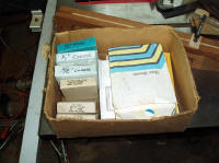
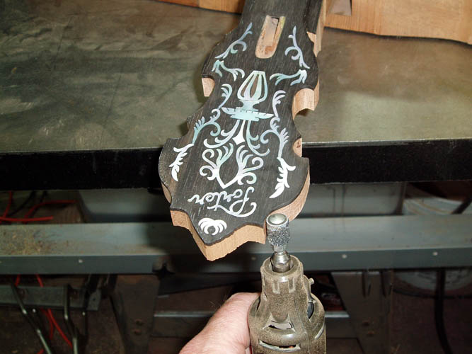
Above pix on the upper left the box where I had the sanding drum no lap
bands aka sleeves sold by William Dixon Company of Carlstadt, NJ that
are over 40 years old. I could not locate a 1/2 inch diameter sanding
drum and had to use a 3/8 inch diameter sanding drum instead. You can
sand the double cut peghead outline with a 1/2 inch diameter sanding drum
but on some early double cut pegheads the lower radius nearer the nut is
closer to 3/8 inch diameter. The 3/8 inch diameter drum was sold by
William Dixon Co., and made of steel. Some of the newer Dremel sanding
drums are made from hard aluminum or soft steel which will bend very easy.
The last pix above shows one that I located in the Dremel accessory box and
needs replacing with a good one made from hardened steel. I guess that
is why it is still in the box waiting on a replacement...grin if you must!.
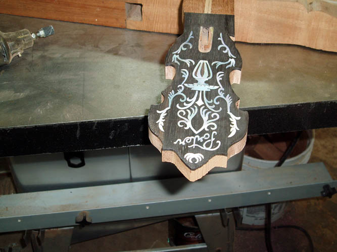
I only used three (3) 3/8 inch diameter coarse sanding sleeves to remove the
band saw marks from the double cut peghead and will finish sand it when the
time comes with finer grades of sand paper rolled onto a wooden dowel.
It didn't take very long too get most of the band saw marks from the peghead
and sanded it fairly close to the thin pencil line tracing of the
double cut peghead template. Not all the templates sold by musical
instrument suppliers are the exact same size as with most of THE GREAT
DEPRESSION ERA Mastertones. The oscillating spindle sanders are
very affordable and most small and/or custom shops have them in their tool
inventory and invaluable for sanding the tight radius on instrument
pegheads, etc. I think I just planted a seed for one.


Today is May 29, 2010 and one of those days when my "biorhythms" were at a
low ebb....grin if you must! I will try and explain as I go. In
this sequence of pixs, I installed the inlaid fingerboard onto the
rectangular shaped neck blank which has a good portion of the heel already
shaped to fit the "pot assembly"; think banjo not
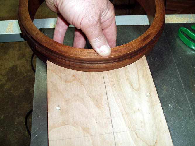
the plant! The first pix is where I trial
fitted the fingerboard snuggled up tight against the nut blank which
was the proper width and unfitted as to height and length at this stage of
construction. I traced the fingerboard overhang at the heel with a
regular lead pencil and cut the radius on the scroll saw. After
cutting the radius, I hand sanded the curve using a left over radius portion from an
earlier heel fixture and simply placed a piece of 150 grit sandpaper
between the radius/fingerboard and hand sanded the fingerboard end to clean up the
scroll saw blade marks. Next was to cut a couple alignment pins to
position the fingerboard onto the neck blank to keep it from moving while
gluing in place. Normally, this is a very simple task; cut the pins aka
small nails to length and drill a hole the proper size/length at each end of the
fingerboard to keep it from skewing while gluing to the neck blank.
After drilling the holes to depth in the fingerboard and leaving 1/8 inch or
less proud of the neck blank, I positioned the fingerboard in the exact position
needed and pressed downward onto the fingerboard or you could tap it with a
small hammer or mallet
to leave a witness mark where you need to drill a matching hole for the pin
aka nail. A few words of caution, use a piece of tape onto the drill
bit as a depth gauge to keep from drilling through your neck blank and
fingerboard. As I said earlier, this is a simple task but it took
several attempts to get it right. My smallest drill press chuck was
too large for the small .073 inch drill bit and didn't have an adapter,
therefore I used a portable battery drill and the drill bit wandered while
drilling into the hard ebony fingerboard. The pin at the nut end of
the fingerboard was a little too long so instead of taking it to the bench
grinder, I elected to file it with a large bastard file and nicked the
peghead overlay which will require a little touch up sanding. I should have used a very
small tapered drill bit to get a pilot hole started for the .073 drill bit
into the fingerboard and could have used the small drill press but didn't
think of that until after the fact. Now, you can see why my biorhythms
are way low. There are days like today and most of the time it is best
to put things down and come back another time or day. After getting the fingerboard
alignment pins installed and positioned correctly, I used a 1/4 inch thick piece of
aluminum the same profile shape of the fingerboard as a gluing caul to keep
from marring the fingerboard from the clamps and help spread the pressure
from the clamping devices. Franklin
Titebond Original glue was evenly spread onto the fingerboard using the tip
of a finger....such much for high tech glue applicators....grin again if you
must! I think I used most of the C clamps that I have and after
gluing, I scraped off the excess glue that squeezed from the edges of the
fingerboard after it became tacky and this will save some sanding/scraping when it gets time to
install the neck binding. Several makers use a flat piece of metal
substrate material and place the fingerboard/neck blank on top of the heavy
flat substrate and glue it in that fashion. However, I want to see the
position of the fingerboard being glued onto the neck blank to verify
nothing has slipped or moved. I know one excellent Craftsman that uses
his table saw to support the fingerboard while applying the clamps and that
is about as flat a surface as you need. If doing necks on a regular basis, a
drill fixture with hardened steel drill bushings to center your neck blank
onto your shaping fixture with matching set up for the fingerboard would be
an easier way to align the fingerboard to the neck blank for gluing;
the same drill fixture would work for both the neck blank and the
fingerboard and also used to position an un-slotted fingerboard onto a sled
at your fret slotting machine. First Quality Music Supply has three
(3) alignment holes drilled into the back of their slotted and profiled
fingerboards which is part of their fixture process for the
fingerboard slotting operation and/or positioning the fingerboard onto their
neck blanks. There has been much heated discussion as
to the orientation of the 5 string fingerboard onto the neck blank because
the fret slots are at a right angle to the fingerboard blank while it is still in
the rectangular shape and after it is profiled. However, when aligning
the profiled fingerboard onto the neck blank, I
align the center of the fingerboard at the nut with the center of the
truss rod and the same at the 22nd fret overhang and it has worked for me in
the past allowing the third (3rd) string to be basically centered down the
fingerboard once past the 5th fret. The fret slots will be off a few thousands of an inch from
perfect perpendicular with the orientation of the centered truss rod but the nut
will be parallel to the fingerboard abutting it and the bridge will be
offset the same amount so again, "Six of one and half a dozen of
another". It would take a very keen eye to
notice a few thousands of an inch from a perfect perpendicular orientation
of the fingerboard to the center of the neck blank. A proper heel
radius cut/fit to the pot assembly is imperative for everything to be
centered.
As I continue with this personal project, I am respecting the custom banjo
builders and musical instrument repair personnel more and more for their
dedication, experience, knowledge and talents! In a brief summation
and personal evaluation up to this point; there is a good parallel that can
be made for knowing how to do something and the actual putting into action
of what you know. There simply is no substitute for the continued
experience of doing something and the cliché "If you don't use it, you
loose it". No longer time that I have devoted to this project,
I have seen an improvement in my instrument wood working skills and a couple
weeks of continued cutting inlays would probably get my eye/hand
coordination back into sync again. However, I am not kidding myself
because I know I am a very, very long way from my former skills but the level of
self satisfaction and enjoyment is extremely high!
Bill Aka Mickey Porter 06-02-10.
Today is 06-10-10 and had some time to devote to this banjo project and
wanted to finish a little fixture/jig I started to aid in cutting the radius
portion of the neck heel where the tube rests. What prompted this
Rube Goldberg fixture was because I could not find a gouge or
carving tool with the proper radius for the fitting of the tube and did not
have a small router bit to fit the Dremel tool or the air mini-die grinder
and ordered a 3/8" diameter carbide sphere. The small carbide sphere
was oversize and decided to go with it anyway since I had rather have it
oversize than undersized and it want hurt a thing. However, it will
not fit like a glove but the tube should not be abutting the neck heel with
any pressure to dampen any neck vibrations but then you could argue that a
snug contact fit helps transfer the vibrations but I don't have scientific
definitive experiment data such as sound recordings and graphs to validate
this. Below a few pixs of the fixture/jig from start to finish::

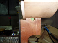
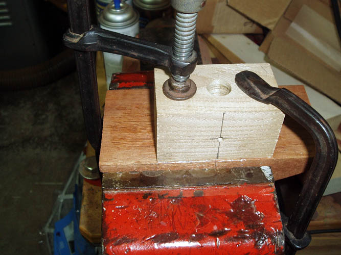
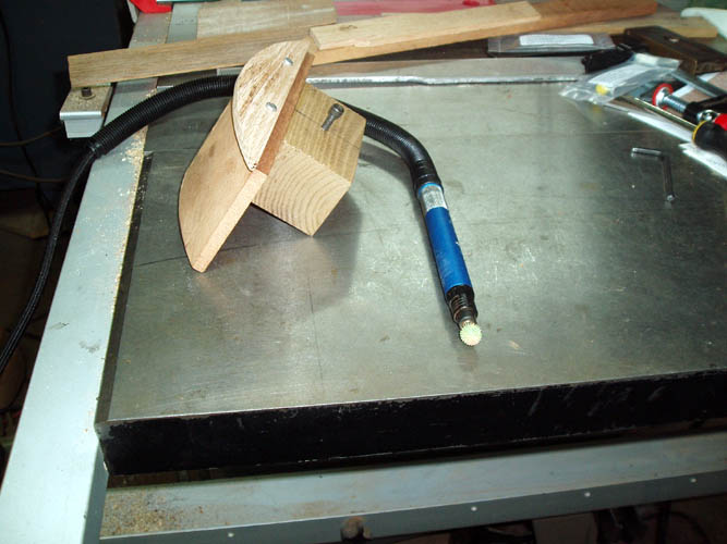
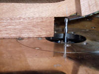
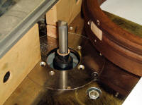
I started out with some scrap Mahogany wood and cut a 5.5" radius freehand
using the band saw and glued a block on top to hold the 5/8 inch diameter
housing of the air powered Mini-Die Grinder. A few measurements were
taken to position the 5/8 inch diameter hole to allow the edge of the
fixture to ride against the cut-out in the neck heel for the tension hoop.
A small guide was attached to the side of the radius fixture to keep the 3/8
inch diameter sphere centered into the 3/8 inch diameter hole that was
drilled straight through the neck heel. This fixture will simply cut
the 5.5inch radius for the tube. After the glue set up overnight, I
drilled the hole for the housing and drilled and tapped a 10-24 tpi hole for
a socket head screw that will secure the min-die grinder in place for the
proper depth of cut. Again, this is a lot of fixture for such a small
task that could be done freehand in a minute or two but I do love making
fixtures and jigs, whether out of wood or metal.....grin if you must!
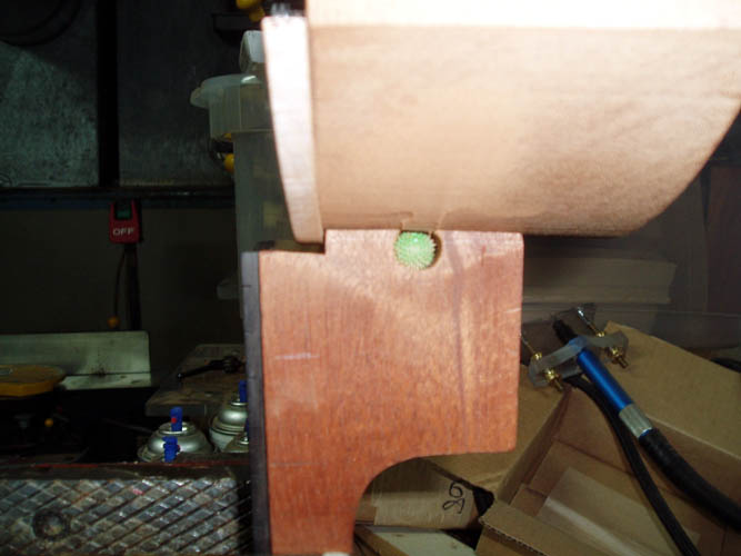
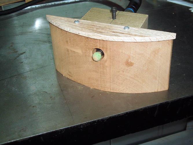
The little fixture worked as planned and had to position the fixture on top
of the neck heel for a pix which doesn't really show the true cut made.
I could have made an adjustable fence on the left side of the radius block
and the screws are long enough to move the cutter if spacers are placed
between the guide and the radius block but calculated the position of the
mini-grinder pretty close to what I needed. I guess the next area will
be to install the frets and cut the extra material width of the neck
material away close enough to allow for the installation of the neck
binding. I am going with the easy fret installation and will install
them like Gibson even though they don't look as pretty as the overhanging
frets onto the binding. That fret installation in my opinion takes
much more experience than the frets flush with the edge of the fingerboard
and you are going to either file frets or file bindings....elbow grease
either way. I hope my 40 year old files will have enough cut left for
this project...grin again.
INSTALLING FRETS
Today is June 20, 2010 Father's Day and have a few spare hours to piddle
with my banjo project and decided to install the
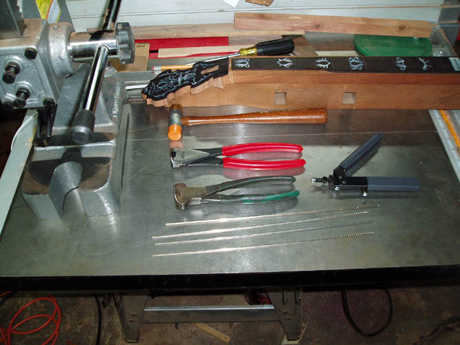
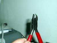
frets. I rounded up
the tools needed and still have an old pair of end nippers (green handle
ones) that I reground to make them full flush cut back in the late
1960s. However, it has seen some bad times since I apparently have cut
some hard tempered wire with them and broke chips out where the cutting edge
is needed for fret trimming. I ordered a fresh pair from StewMac and
back when I first started doing instrument repair, building, etc.; you had
to more or less fabricate and modify tools of which they are now readily
available such as the fret nippers, files, etc.
I pressed frets into their final position when I was in the music business
with a custom made press made by Bill Benson (deceased) of Southern Pines,
NC who was an excellent machinists and general fixer for a textile plant or
one that manufactured textile machines and components. Bill and myself
did a lot of "horse trading" on things that helped each of us back in the
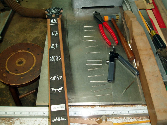
early 1970s. Below a few pixs and I went off
"half cocked"
on this one by cutting the fret wire too long and ran short a fret or two
and have two other different types of banjo fret on hand and had to order
some on the Internet a little while ago and they were out of stock which is
hard to believe for such a large company.


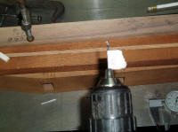
I have a small one ton arbor press and had a local machinists bore a 3/8
inch diameter hole centered in the arbor to receive the
Stew Mac Fret Press Caul # 4365 and I drilled and tapped an 8-32 hole for a set
screw. My large drill press was "tied up" with a multipurpose turkey
box call lid drilling operation and my machinists friend said, he knew it
would not be easy since his milling machine throat depth was too short and
had to bore the hole using his lathe and a 4-way chuck...I had to grin too! This little press is a very long way from being as good as the
one Bill Benson made for me and I immediately didn't like it. It was
too much trouble to align the brass insert for the fret wire and didn't
like the leverage factor on this particular press although pressing frets
into place is a much better fail safe method for new construction or that is
my opinion anyway whether right or wrong...it worked for me decades ago.
It was difficult to actually feel when the fret
was fully seated into the fingerboard and I am sure it is the
"fault" of the
little press and/or my lack of experience using this press for fret
installation. My old fret press had two vertical
heavy duty upright rams coming from a geared box and had a humungous heavy weight
flat horizontal bar secured onto each upright ram and had plenty of room and
vertical movement of the rams to maneuver a
neck black with the fret board and could easily place heavy metal cauls
under the curvature of the neck blank where needed. I got rid of
pressing the frets into place very
quickly and went back to the traditional hammer method only and tapped the
frets into place and bent the overhanging fret ends downward slightly.
I can't remember what happened to my old custom made fret hammer which I
think was a modified ball peen hammer but could be wrong since that was 41
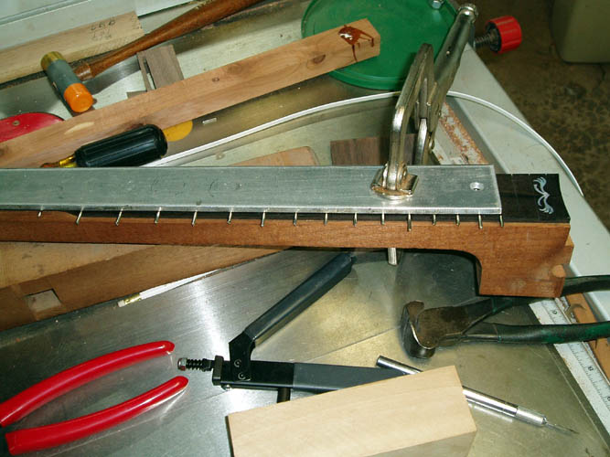
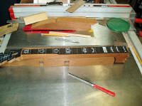
years plus ago. However,
the wooden neck support had to much bounce and give to it and dragged
out a two foot section of railroad train track and that gave the support
needed and I could feel and hear the difference when the fret was seated
fully.
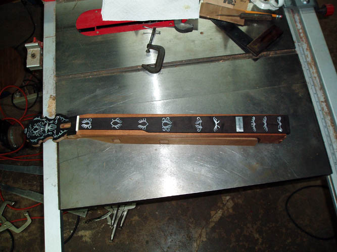
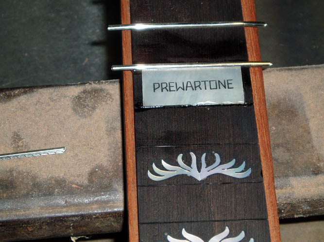
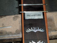
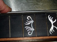
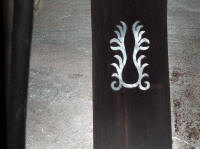
My PREWARTONE mother of pearl block is at the 15th fret and from fret
line to fret line and had already tapered the inside edges of the mother of
pearl block and placed some Epoxy 330 into the 14th and 15th fret slot and
hammered the frets into place and used the 1/4 inch thick aluminum
fingerboard profile plate to C clamp the frets until the epoxy has set.
When I get additional fret wire, I will install the last few frets and trim
the ends flush with the fingerboard and then install the neck binding.
The fret wire came in today 06-24-10 and installed the last few frets and
trimmed the ends with a Stewart MacDonald
fret cutter # 0619. I used a Stew Mac
3-Corner Fret Dressing File # 1603 which is 9 inches in length.
You can make your own if you desire by grinding the edges smooth on a large
mill Bastard fine cut flat file or a large triangular file which will allow
you to file the ends of the frets flush with the fingerboard and not remove
any material from the neck blank where the binding will rest. This
file will also allow you to taper the fret ends without damage to the
fingerboard which is a plus also. You need a good smooth flat surface
for the binding and/or wood purfling to rest against otherwise it will show
up badly when glued into place. If you are routing into the neck
blank, there would be no problem filing the fret ends with a regular file
but one that doesn't cut on the narrow edge of the file works much better.
A flush cut carbide router bit with a bearing could be used to trim the fret
ends but would be more trouble than it would be worth for only one neck.
My fret installation was not perfect but not too bad either since I have not
installed frets in 10 plus years. It want take but a little touch up
to level a couple frets around the 5th to the 7th frets and string tension
might pull the neck up just a little without working the truss rod any.
NOTE: I didn't like the looks of a couple of the frets; not
perfectly level and up a little at the ends and pulled them and glued and
pressed in new ones. The brittle ebony around the edge of the fret
slot pulled up in a couple places and will require some TLC to get
100 percent eye appeal!
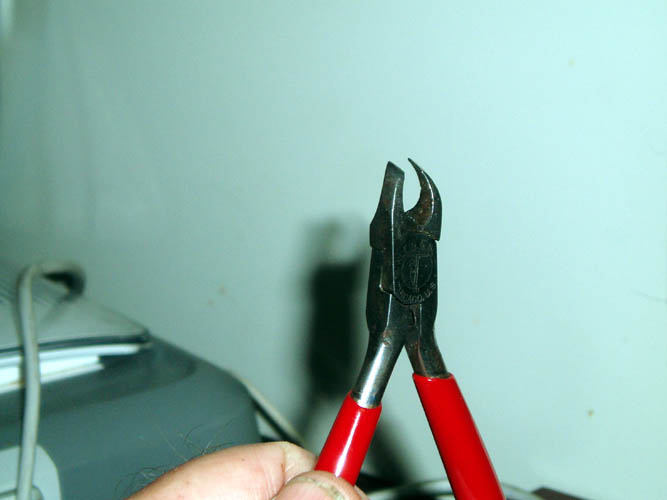
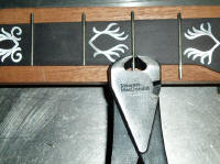
The above pix on the far right is a tool that I used to remove the frets and
will allow you to lift a fret from the fret slot and will trap the wood
below the fret wire while lifting the fret wire upward in small increments.
You start at one end of the fret wire and slowly work your way across the
fingerboard until the entire fret is removed. When you place the jaws
on each side of the fret wire and press inward, the fret will lift and the
radius portion of the jaws will remain tightly against the fingerboard
trapping the wood in place with much less wood tear out than any tool I have
ever used. The tool was made by Klein & Sons and the number stamped on
the side is 263-40. This tool was designed for nipping/cutting
"full flush" components from electronic circuit boards and has been in my
tool box since around 1968 or so. It has also served to clip the
ends of monofilament fishing line when I made a knotted leader using a
barrel knot for joining two different sizes of monofilament line together.
INSTALLING INLAID HEEL CAP
I plan to inlay and install a heel cap on this neck and will cut the heel
height down about .090 inches before gluing the heel cap in place and will
have to "rig a jig" to cut the taper on the flat portion of
the neck heel. I don't have an adjustable taper slide for my
table saw and could just as easily freehand the cut and sand it flat of
which I might do that anyway....grin if you must!
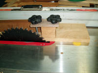
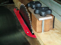
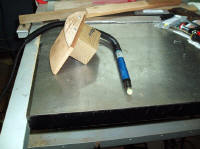
This simple little jig was not really necessary but I enjoyed drilling a few
extra holes and had the T bolts and threaded knobs so what the heck!
If this jig was used more than once, I would install a wooden guard and an
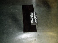
upright knob for proper hand position for increased safety from the saw
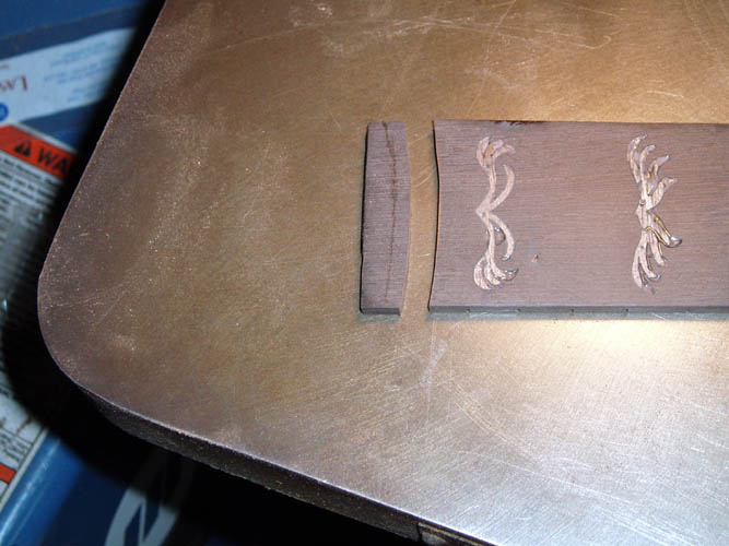
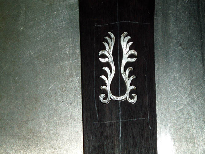
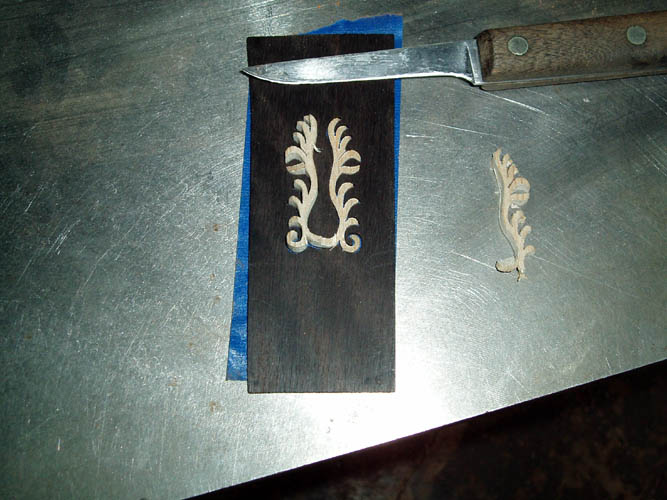
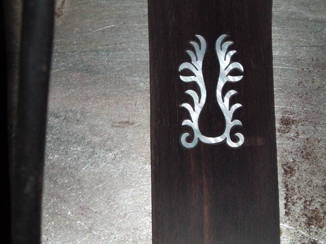
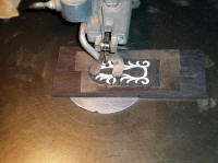
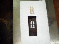
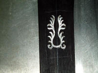
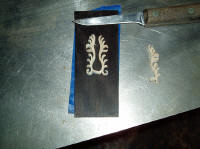
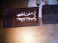
blade. I found a mother of pearl "Flaming Claw" heel cap inlay cut from the
mid 1970s in my machinists tool box and above pixs of cutting the ebony heel
cap material to receive the inlay. I have already touched bases with
the cutting and inlaying process earlier and this is a short recap or
Reader's Digest version of the process.
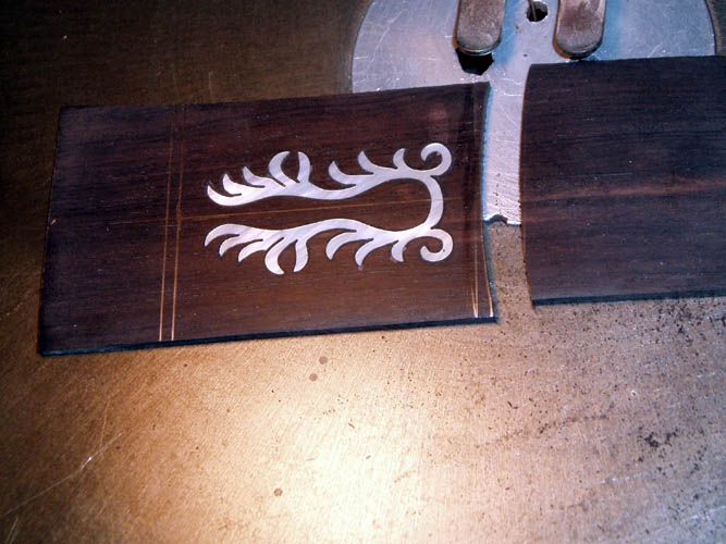
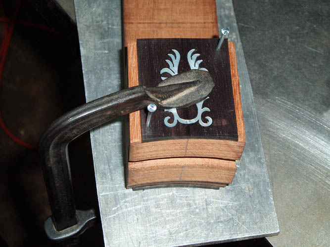
After inlaying, sanding and cutting the heel cap to the radius of the neck,
I drilled a couple .073 diameter alignment holes in excess heel wood to pin
the heel cap in position while gluing and clamping. I drilled a couple
3/16 inch diameter holes in a piece of scrap walnut wood for usage as a caul
which allows the nails aka alignment pins to protrude of which will be
pulled out after the glue has dried overnight.
After the heel cap installation,
I will then mark a line a little over .040 inches from the edge of the
fingerboard and band saw the excess neck blank material away leaving only
enough room to install the neck binding. I haven't decided whether I
will use a plain piece of white binding or add a .020 black and .020 white
underneath the 3/16 or 1/4 inch white binding.
LEAVING ON A
SPIRITUAL NOTE
If you do not know Jesus Christ as your Lord and Savior, please take
this moment to accept him by Faith into your Life, whereby Salvation
will be attained.
Ephesians 2:8 - 2:9 8 For by grace are ye saved through
faith; and that not of yourselves: [it is] the gift of God: 9 Not of
works, lest any man should boast.
Hebrews 11:1 “Now faith is the substance of things hoped for,
the evidence of things not seen.”
Romans 10:17 “So then faith cometh by hearing, and hearing by
the word of God.”
Open this
link about faith in the King James
Bible.
Romans 10:9 “That if thou shalt confess with thy mouth the
Lord Jesus, and shalt believe in thine heart that God hath raised him
from the dead, thou shalt be saved.”
Open this
link of Bible Verses About Salvation,
King James Version Bible (KJV).
Hebrews 4:12 “For the word of God is quick, and powerful, and
sharper than any two edged sword, piercing even to the dividing asunder
of soul and spirit, and of the joints and marrow, and is a discerner of
the thoughts and intents of the heart.”
Romans 6:23 “For the wages of sin is death; but the gift of
God is eternal life through Jesus Christ our Lord.”
Romans 3:23 “For all have sinned, and come short of the glory
of God;”
Micah 6:8 “He hath shewed thee, O man, what is good; and what
doth the LORD require of thee, but to do justly, and to love mercy, and
to walk humbly with thy God?”
Philippians 4:13 "I can do all things through Christ which
strengtheneth me."
PREVIOUS PAGE
NEXT PAGE
BANJO CONSTRUCTION HOME PAGE